
Power transformer comprehensive monitoring system

A monitoring system and transformer technology, applied in the direction of measuring electrical variables, instruments, measuring electricity, etc., can solve the problems of insufficient installation pertinence, low detection rate, heavy detection workload, etc., achieve reliable and effective methods, and accurate and reliable detection results letter, to avoid the effect of transformer failure

Inactive Publication Date: 2018-10-02
STATE GRID SHANDONG ELECTRIC POWER +2
View PDF6 Cites 19 Cited by
  • Summary
  • Abstract
  • Description
  • Claims
  • Application Information

AI Technical Summary

Problems solved by technology

[0005] 1) A large number of test personnel lack the technical ability of state detection such as partial discharge, and fail to find latent defects according to the detected signals;
[0006] 2) When a suspected defect or a non-emergency defect is detected, it is often necessary to adopt a tracking detection mode. The detection workload is heavy, and the frequency of tracking detection is difficult to guarantee;
[0007] 3) There is a certain degree of randomness in some equipment defects, such as partial discharge signals may appear intermittently, while the duration of traditional live detection is short, and missed detection occurs frequently
[0009] 1) The high investment cost of the traditional online monitoring system limits the expansion of its application scope;
[0010] 2) The defect detection rate of the current online monitoring system is low, and a large number of online monitoring systems are idle
The installation of the system is not targeted enough, and the input-output rate is low
[0011] 3) The online monitoring of the main transformer is mainly based on a single monitoring mode, which cannot cover the location and shape of the transformer body fault, and adopting a single passive monitoring mode cannot provide corresponding auxiliary decision-making means for equipment managers

Method used


Image

  • Power transformer comprehensive monitoring system
  • Power transformer comprehensive monitoring system
  • Power transformer comprehensive monitoring system

Examples


Embodiment Construction

[0042] In order to enable those skilled in the art to better understand the technical solutions in the present application, the technical solutions in the embodiments of the present application will be clearly and completely described below in conjunction with the drawings in the embodiments of the present application. Obviously, the described The embodiments are only some of the embodiments of the present application, but not all of them. Based on the embodiments in this application, all other embodiments obtained by persons of ordinary skill in the art without creative efforts shall fall within the scope of protection of this application.

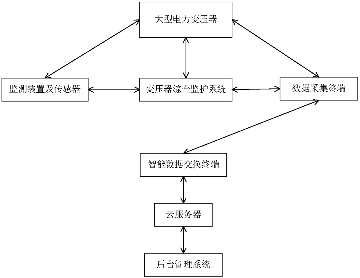
[0043] A transformer comprehensive monitoring system, which includes multiple monitoring devices capable of rapid detection and fault location and external sensors, an outdoor cabinet, a mobile wireless communication network, and transformer internal insulation defect diagnosis system software. Transformer integrated monitoring system can...


PUM


Abstract

The invention discloses a transformer comprehensive monitoring system, which comprises a plurality of monitoring devices capable of rapid detection and fault positioning, external sensors of the monitoring devices, an outdoor cabinet body, a mobile wireless communication network and transformer internal insulation defect diagnosis system software. The transformer comprehensive monitoring system can improve the coping capability of a large-scale power transformer to more complicated operating conditions of an intelligent power grid in the future, and reduce the probability of occurrence of newhidden dangers, thereby improving the reliability of the entire power grid system; and the power transformer comprehensive monitoring system can perform rapid and effective evaluation on insulating states and service life of a large-scale power transformer, effectively instructs the operation and maintenance, reduces the workload of the operation and maintenance personnel, and decreases the operation and management costs.

Description

technical field [0001] The invention designs a transformer protection device, and in particular relates to a transformer comprehensive monitoring system. Background technique [0002] Transformers are important equipment in the power system. Once a serious fault occurs, the power system may be paralyzed. Therefore, when there is a suspected defect in the transformer and the severity and development trend cannot be determined, the transformer will continue to operate with "illness" most of the time, so that Determine the nature of the fault, wait for repairs or buy time for calling a spare transformer. During this period of time, it is necessary to monitor, record, analyze, diagnose and take emergency measures as well as long-term continuous observation and tracking of "sick" transformers. [0003] At present, the state detection of power transformer equipment mainly includes live detection and online monitoring. Although the corresponding technology has been widely used, it...

Claims


Application Information

Patent Timeline
Patent Type & Authority Applications(China)
IPC IPC(8): G01R31/00
CPCG01R31/00
Inventor 刘兴华吕学宾韩克存王涛文珊孔刚于洋巩方伟郑春旭王军魏建莉乔恒崔川季素云岳增伟刘林边宏超刘琳杨超
Owner STATE GRID SHANDONG ELECTRIC POWER
Learn More