
Continuous hydrogenation reduction reaction system

A technology of reaction system and reaction device, applied in the field of continuous hydrogenation reduction reaction system, can solve the problems of no successful industrialization precedent, prolonged reaction period, large area of ​​the reaction kettle, etc., to achieve short product contact time and reduce reaction steps. , the effect of shortening the production cycle

Active Publication Date: 2021-10-01
新疆摩珈生物科技有限公司
View PDF6 Cites 0 Cited by
  • Summary
  • Abstract
  • Description
  • Claims
  • Application Information

AI Technical Summary

Problems solved by technology

However, this high-pressure reactor has many disadvantages: 1. Gas-solid-liquid three-phase reaction must leave enough space for the gas, which leads to a larger reactor, which will make its sealing more difficult. Reduced safety, especially at high pressure
2. Catalyst separation must use other equipment
3. Excess gas can only be discharged directly into the atmosphere, causing pollution and waste of resources
4. Because it is impossible to achieve a good mixture of gas, solid and liquid during the reaction process, the reaction cycle is lengthened
5. The reactor occupies a large area
[0003] At present, the tubular reactor is mainly based on gas-solid reaction. The raw material is gasified at high temperature and passed through the solid-supported catalyst. However, the tubular reactor for gas-solid reaction is only suitable for raw materials with low boiling point and will not decompose at high temperature. range of its use
[0004] The existing gas-solid-liquid three-phase tubular reactor does not solve the problem of solid loading of catalyst and recovery and use of hydrogen, and there is no precedent for successful industrialization

Method used


Image

  • Continuous hydrogenation reduction reaction system

Examples


Embodiment 1

[0030] Example 1 2-chlorouracil is reduced to 2-deoxyuracil

[0031] 1) Add the solid-loaded nickel catalyst into the catalytic reactor. Assemble all the components, pass in 0.2mpa nitrogen gas, check the air tightness, and proceed to the next step if there is no air leakage.

[0032] 2) Add 3kg of 2-chlorouracil to 60kg of methanol to form a 5% methanol solution.

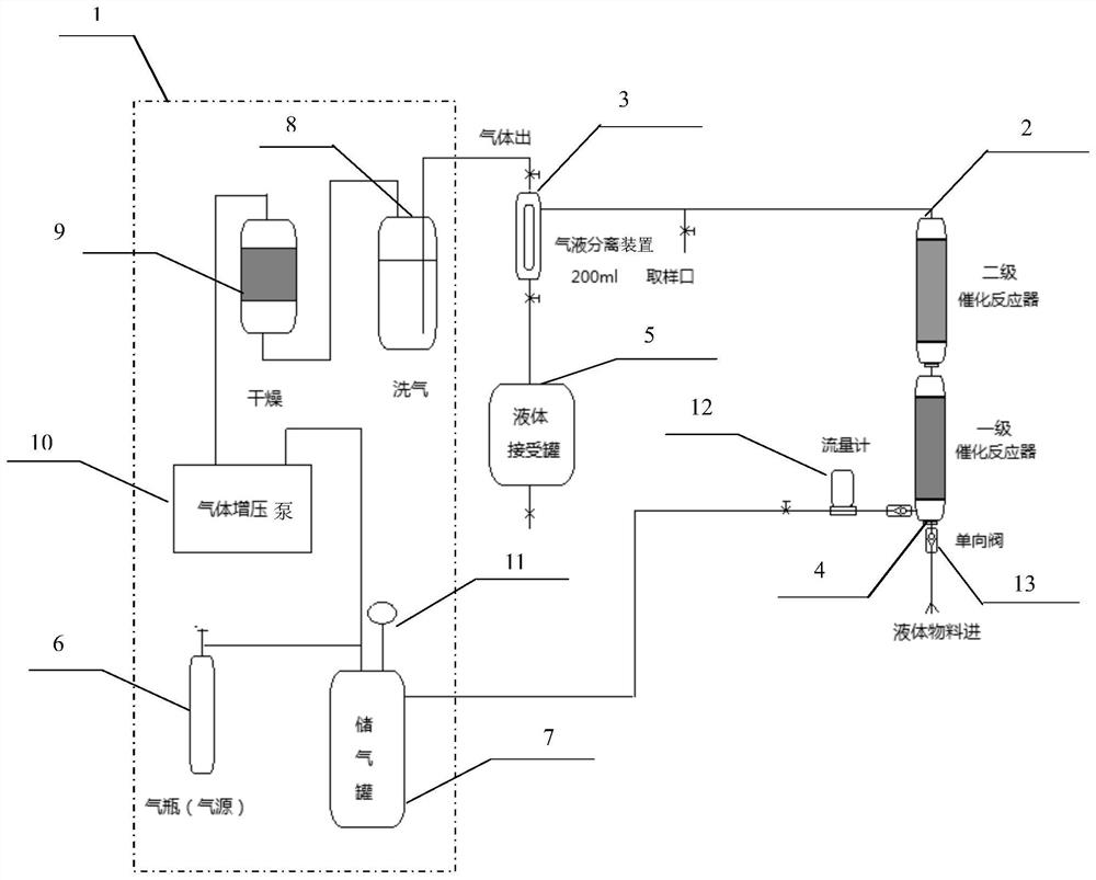
[0033] 3) The whole system is fed with nitrogen gas of 0.1 MPa and vacuumed for three times, then vacuumed and fed with hydrogen gas of 0.1 MPa. Vacuumize, and then the gas storage tank 7 is fed with hydrogen to be constant at 2.0mpa.

[0034] 4) Open the valve of the one-way valve 13 of the liquid material inlet 4 and start to feed pure water, and adjust the valve of the one-way valve 13 of the liquid material inlet 4 to stabilize the feed rate at 20ml / min.

[0035] 5) Turn on the gas booster pump 10, adjust the flow meter 12 to make the gas velocity reach 30 L / min, and then adjust the gas outlet valve of the g...

Embodiment 2

[0039] Embodiment 2 Nitrobenzene is reduced to aniline

[0040] 1) Add the solid-loaded nickel catalyst into the catalytic reactor. Assemble all the components, pass in 0.2mpa nitrogen gas, check the air tightness, and proceed to the next step if there is no air leakage.

[0041] 2) Add 1kg of nitrobenzene to 5kg of ethanol to make a 20% ethanol solution. A nickel catalyst that has been solidly loaded is added into the catalytic reactor.

[0042] 3) The whole system is fed with nitrogen gas of 0.1 MPa and vacuumed for three times, then vacuumed and fed with hydrogen gas of 0.1 MPa. Vacuumize, and then the gas storage tank 7 is fed with hydrogen to be constant at 2.0mpa.

[0043] 4) Open the valve of the one-way valve 13 of the liquid material inlet 4 and start to feed pure water, and adjust the valve of the one-way valve 13 of the liquid material inlet 4 to stabilize the feed rate at 50ml / min.

[0044] 5) Turn on the gas booster pump 10, adjust the flow meter 12 to make the ...


PUM


Abstract

The invention discloses a continuous hydrogenation reduction reaction system, which comprises a hydrogen circulation device, a reaction device and a gas-liquid separation device. The hydrogen circulation device, the reaction device, and the gas-liquid separation device are sequentially connected through pipelines, wherein one of the hydrogen circulation devices One side is connected to the reaction device through a pipeline, and the other side is connected to the gas-liquid separation device through a pipeline. The continuous hydrogenation reduction reaction system of the present invention not only successfully solves the problem of hydrogen recovery and use by recycling hydrogen, effectively saves energy and reduces environmental pollution, but also saves the need for separating the catalyst by adding a solid-supported catalyst in the reactor. Separation of equipment and steps shortens the production cycle, improves production efficiency, and has broad application prospects.

Description

technical field [0001] The invention relates to the field of chemical equipment, in particular to a continuous hydrogenation reduction reaction system. Background technique [0002] At present, the industrial production of hydrogenation reduction reaction mainly uses an autoclave as the reaction vessel. The reaction process is to add the gas-solid-liquid into a reactor, and stir vigorously to fully mix the gas-solid-liquid. However, this high-pressure reactor has many disadvantages: 1. Gas-solid-liquid three-phase reaction must leave enough space for the gas, which leads to a larger reactor, which will make its sealing more difficult. Reduced safety, especially at high pressures. 2. The separation of the catalyst must use other equipment. 3. Excess gas can only be discharged directly into the atmosphere, causing pollution and waste of resources. 4. Because the gas-solid-liquid fully mixed in the reaction process cannot achieve a good result, resulting in a longer reaction...

Claims


Application Information

Patent Timeline
Patent Type & Authority Patents(China)
IPC IPC(8): B01J8/04B01J8/06C07H19/073C07H1/00C07C209/36C07C211/46
CPCB01J8/0005B01J8/0278B01J8/04B01J8/0492B01J8/06C07C209/36C07H1/00C07H19/073C07C211/46Y02P20/129
Inventor 陈彦于晓锋邱贵森
Owner 新疆摩珈生物科技有限公司
Learn More