Charging pile for electric vehicle

A technology for electric vehicles and charging piles, which is applied in the direction of electric vehicle charging technology, electric vehicles, charging stations, etc., can solve the problems that charging piles cannot protect themselves, achieve significant anti-collision effects, simple and stable structures, and prevent charging piles from being damaged Effect

Inactive Publication Date: 2018-10-09
HUANGHE S & T COLLEGE
View PDF7 Cites 15 Cited by
  • Summary
  • Abstract
  • Description
  • Claims
  • Application Information

AI Technical Summary

Problems solved by technology

[0007] In view of the above situation, in order to overcome the defects of the prior art, the present invention provides an electric vehicle charging pile, which effectively solves the problem that the existing charging pile cannot protect itself, and cannot prevent the charging pile from being damaged or even exploded due to a mistake in reversing the electric vehicle. The problem

Method used


Image

  • Charging pile for electric vehicle
  • Charging pile for electric vehicle
  • Charging pile for electric vehicle

Examples


Embodiment 1

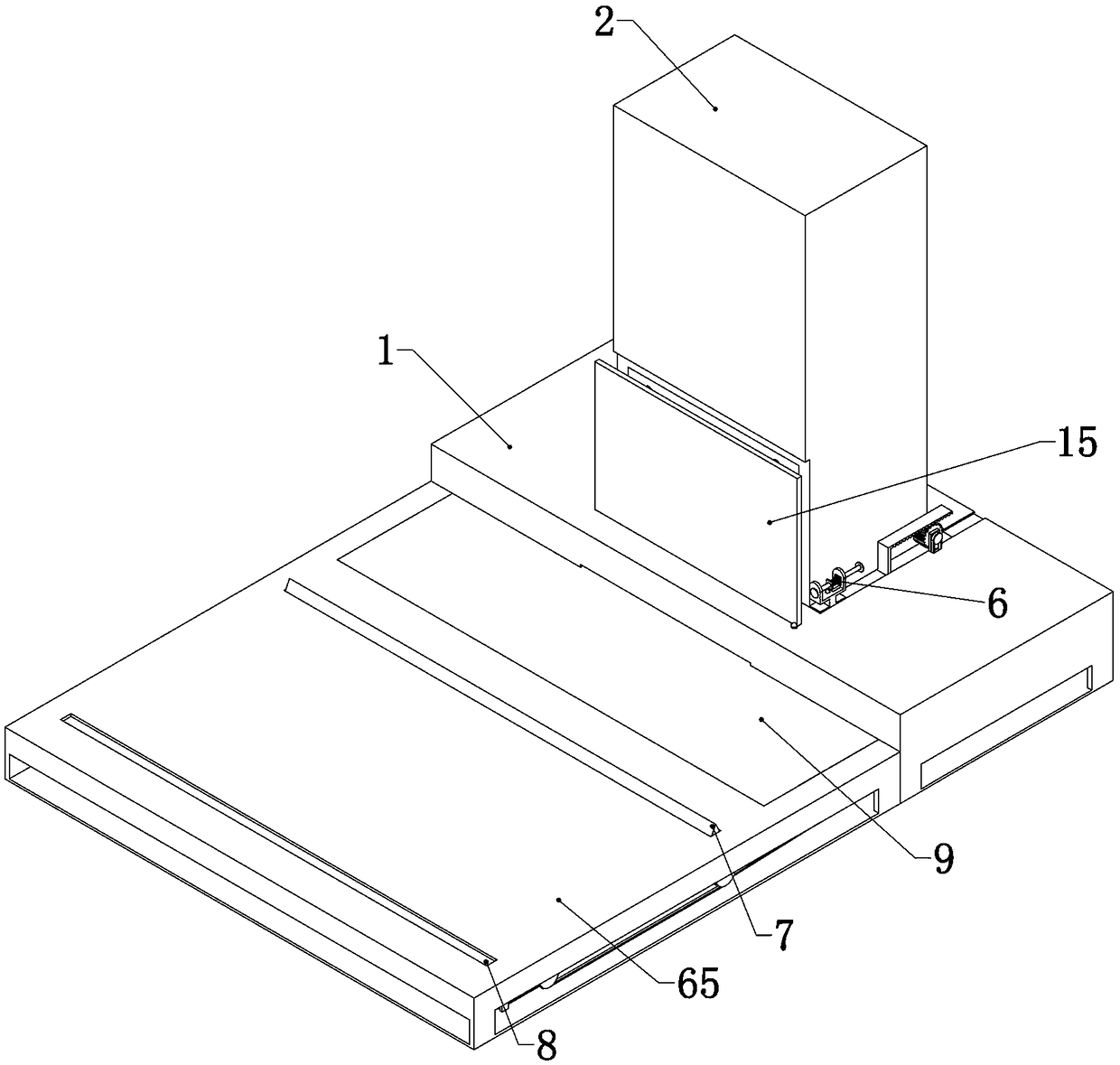
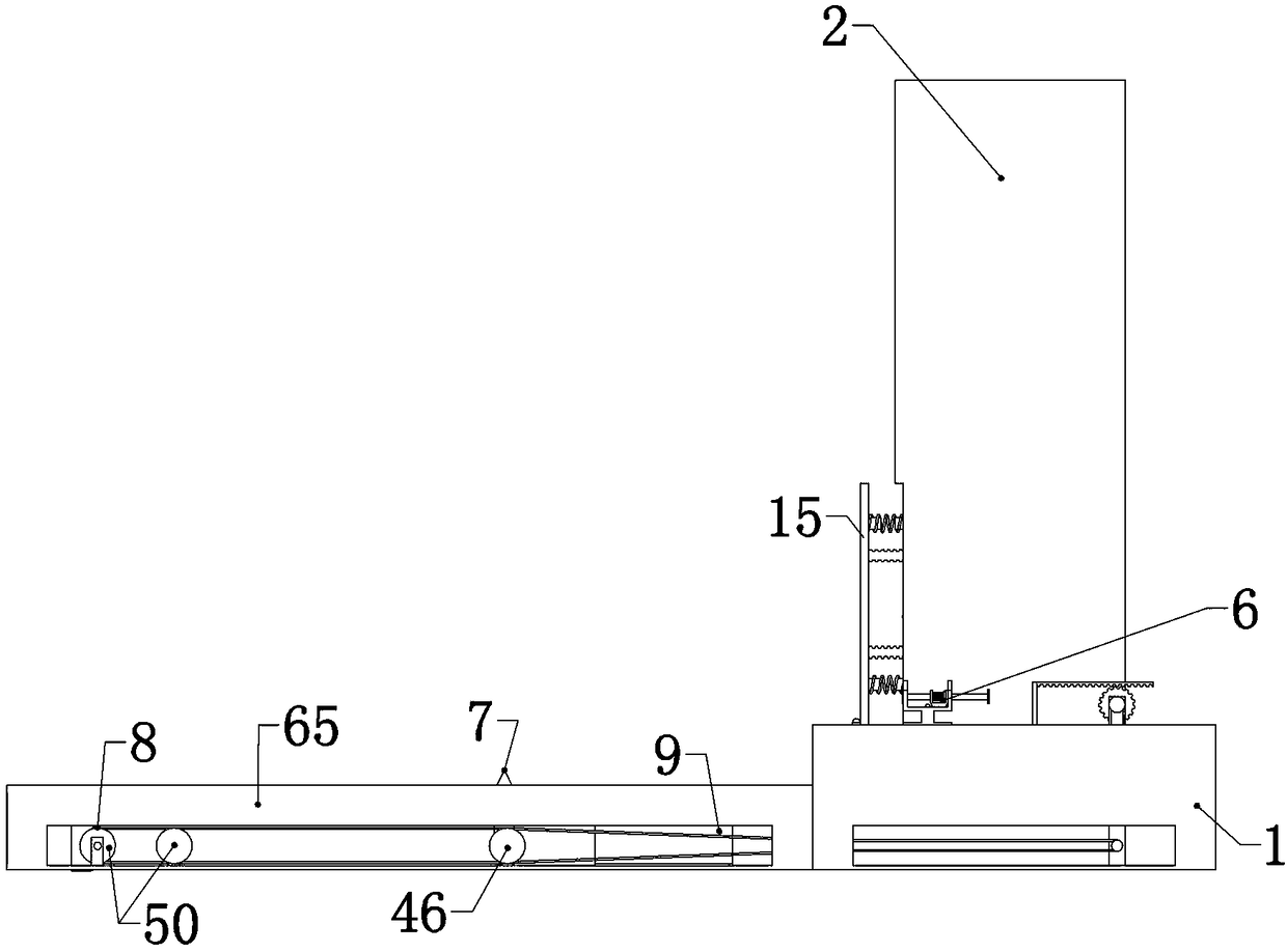
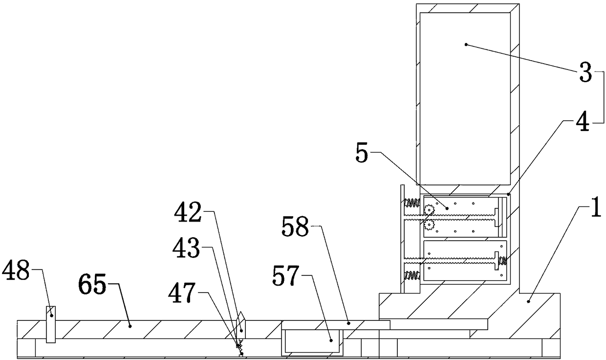
[0035] Embodiment 1, the present invention is an electric vehicle charging pile, including a base 1, the base 1 is the fixed foundation for the follow-up structure, and the base 1 is fixedly connected with a box body 2, which is characterized in that the box body is divided into two parts It consists of upper and lower layers, which are called upper box 3 and lower box 4 respectively. The upper box 3 has a built-in charging pile charging system, and the existing charging pile charging system is set high. In addition to facilitating the installation of subsequent structures in the lower part , can also prevent rainy weather and other weather accumulations of water from flooding into the charging system, resulting in a short circuit and fire on the charging pile. The lower box 4 is a cavity with an open front end, and the lower box 4 is built with a buffer for slowing down the impact of the vehicle. Box 5, the buffer box 5 can buffer the impact received, the buffer box 5 is slidi...

Embodiment 2

[0038] Embodiment 2. On the basis of Embodiment 1, the delayed impact device 6 includes a fixed seat 23 placed on the side of the box body 2 and fixed on the base 1. The fixed seat 23 is "U" shaped, and the fixed seat 23 is A corresponding through hole 24 is provided on the two walls of the seat 23, and a striking rod 25 is slidably connected in the through hole 24. the inner side of the buffer front plate 15, and thus push the buffer front plate 15 out, the other end can touch the push rack 20, and the impact rod 25 is sleeved with a sliding connection U-shaped block 26, the U-shaped block 26 is provided with an impact spring 27 sleeved on the striking rod 25, one end of the impact spring 27 is fixedly connected to the side wall of the U-shaped block 26, and the other end of the impact spring 27 is fixedly connected On the striking rod 25, the bottom surface of the fixed seat 23 is provided with a small block 28 that can move up and down. When the U-shaped block 26 slides, th...

Embodiment 3

[0039] Embodiment three, on the basis of embodiment one, described buffer tank 5 comprises buffer tank casing 10, and buffer tank casing 10 is double-layer cavity up and down and is respectively called buffer tank upper cavity 11, buffer tank lower space Cavity 12, the upper cavity 11 of the buffer box and the lower cavity 12 of the buffer box are respectively equipped with an upper movable plate 13 and a lower movable plate 14 that can slide therein, and the upper movable plate 13 and the lower movable plate 14 are integrated A buffer front plate 15 placed outside the front end of the buffer box 5 is connected, and the upper movable plate 13 and the lower movable plate 14 are respectively connected with the upper buffer structure 16 and the lower cavity 12 of the buffer box placed in the upper cavity 11 of the buffer box. The inner lower buffer structure 17 is connected, that is, after the buffer front plate 15 is impacted, it will be transmitted to the upper buffer structure ...


PUM


Abstract

The invention relates to an electric vehicle charging pile. The electric vehicle charging pile effectively solves the problem that an existing charging pile cannot prevent the charging pile from beingdamaged due to reversing mistakes. According to the technical scheme, the electric vehicle charging pile comprises a base, wherein the base is fixedly connected with a box body. The electric vehiclecharging pile is characterized in that the box body is divided into an upper layer and a lower layer, and the upper layer and the lower layer are correspondingly called an upper box body and a lower box body; the upper box body is internally provided with a charging pile charging system; the lower box body is a cavity with an opening at the front end; the lower box body is internally provided witha buffer box for reducing and slowing down vehicle impact; a buffer front plate is slidably connected to the inner portion of the buffer box, wherein one end of the buffer front plate is arranged outside the front end surface of the buffer box; and a delay impact device fixed on the base is arranged at the side of the box body, and a triggering device connected with the delay impact device for triggering the delay impact device is arranged at the front end of the base. The electric vehicle charging pile effectively prevents the charging pile from being damaged and the secondary damage causedby the impact of the electric vehicle backing into the charging pile.

Description

technical field [0001] The invention relates to the technical field of new energy vehicle charging piles, in particular to an electric vehicle charging pile. Background technique [0002] Under the background of energy constraints and environmental pollution, the country regards the development of new energy as an important measure to improve the environment and save costs. Among them, with continuous efforts, the new energy automobile industry has shown a good momentum of development in recent years. Electric vehicles are favored by the majority of users because of their low cost of use, easy maintenance, stable driving, no impact in shifting gears, and environmental protection, and have quickly become the most important part of new energy vehicles. Major automobile manufacturers are also vigorously developing the electric vehicle industry in response to market demand and the country's call, making electric vehicles have made great progress in recent years. [0003] As an...

Claims


Application Information

Patent Timeline
Patent Type & Authority Applications(China)
IPC IPC(8): B60L11/18E04H6/42
CPCB60L53/31E04H6/42Y02T10/70Y02T10/7072Y02T90/12Y02T90/16
Inventor 方凯沈亚敏赖东虎杜天奇
Owner HUANGHE S & T COLLEGE
Why Eureka
Try Eureka