An electric vehicle charging pile
A technology of electric vehicles and charging piles, which is applied in the direction of electric vehicle charging technology, electric vehicles, charging stations, etc., can solve the problems that charging piles cannot protect themselves, achieve significant anti-collision effects, simple and stable structure, and prevent charging piles from being damaged Effect
- Summary
- Abstract
- Description
- Claims
- Application Information
AI Technical Summary
Problems solved by technology
Method used
Image
Examples
Embodiment 1
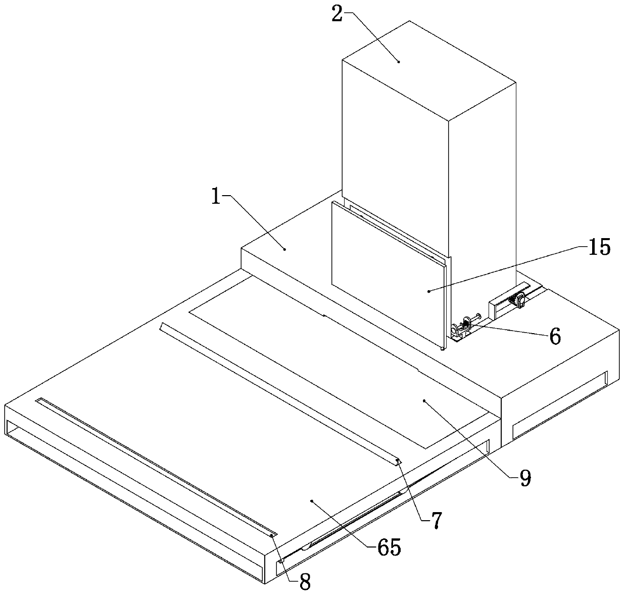
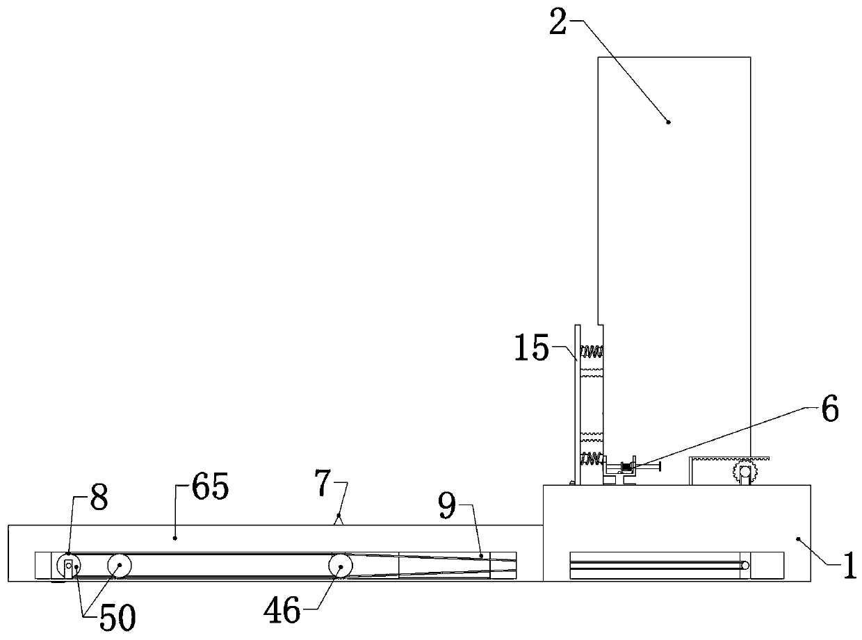
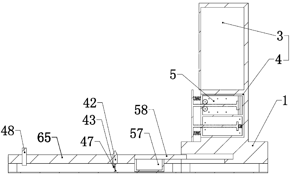
[0035] Embodiment 1, the present invention is an electric vehicle charging pile, including a base 1, the base 1 is the fixed foundation for the follow-up structure, and the base 1 is fixedly connected with a box body 2, which is characterized in that the box body is divided into two parts It consists of upper and lower layers, which are called upper box 3 and lower box 4 respectively. The upper box 3 has a built-in charging pile charging system, and the existing charging pile charging system is set high. In addition to facilitating the installation of subsequent structures in the lower part , can also prevent rainy weather and other weather accumulations of water from flooding into the charging system, resulting in a short circuit and fire on the charging pile. The lower box 4 is a cavity with an open front end, and the lower box 4 is built with a buffer for slowing down the impact of the vehicle. Box 5, the buffer box 5 can buffer the impact received, the buffer box 5 is slidi...
Embodiment 2
[0038] Embodiment 2. On the basis of Embodiment 1, the delayed impact device 6 includes a fixed seat 23 placed on the side of the box body 2 and fixed on the base 1. The fixed seat 23 is "U" shaped, and the fixed seat 23 is A corresponding through hole 24 is provided on the two walls of the seat 23, and a striking rod 25 is slidably connected in the through hole 24. the inner side of the buffer front plate 15, and thus push the buffer front plate 15 out, the other end can touch the push rack 20, and the impact rod 25 is sleeved with a sliding connection U-shaped block 26, the U-shaped block 26 is provided with an impact spring 27 sleeved on the striking rod 25, one end of the impact spring 27 is fixedly connected to the side wall of the U-shaped block 26, and the other end of the impact spring 27 is fixedly connected On the striking rod 25, the bottom surface of the fixed seat 23 is provided with a small block 28 that can move up and down. When the U-shaped block 26 slides, th...
Embodiment 3
[0039] Embodiment three, on the basis of embodiment one, described buffer tank 5 comprises buffer tank casing 10, and buffer tank casing 10 is double-layer cavity up and down and is respectively called buffer tank upper cavity 11, buffer tank lower space Cavity 12, the upper cavity 11 of the buffer box and the lower cavity 12 of the buffer box are respectively equipped with an upper movable plate 13 and a lower movable plate 14 that can slide therein, and the upper movable plate 13 and the lower movable plate 14 are integrated A buffer front plate 15 placed outside the front end of the buffer box 5 is connected, and the upper movable plate 13 and the lower movable plate 14 are respectively connected with the upper buffer structure 16 and the lower cavity 12 of the buffer box placed in the upper cavity 11 of the buffer box. The inner lower buffer structure 17 is connected, that is, after the buffer front plate 15 is impacted, it will be transmitted to the upper buffer structure ...
PUM
 Abstract
Description
Claims
Application Information
 - R&D
- Intellectual Property
- Life Sciences
- Materials
- Tech Scout
- Unparalleled Data Quality
- Higher Quality Content
- 60% Fewer Hallucinations
Browse by: Latest US Patents, China's latest patents, Technical Efficacy Thesaurus, Application Domain, Technology Topic, Popular Technical Reports.
© 2025 PatSnap. All rights reserved.Legal|Privacy policy|Modern Slavery Act Transparency Statement|Sitemap|About US| Contact US: help@patsnap.com


