
Rapid clamping and lifting equipment for motor equipment

A technology for hoisting equipment and electromechanical equipment, applied in the field of clamping and hoisting electromechanical equipment, can solve problems such as difficulty in fast fixing, and achieve the effects of good sealing, good buffering, and stable adsorption and clamping.

Inactive Publication Date: 2018-10-09
苏州睿鑫莱机电科技有限公司
View PDF4 Cites 10 Cited by
  • Summary
  • Abstract
  • Description
  • Claims
  • Application Information

AI Technical Summary

Problems solved by technology

The general concept of electromechanical equipment in modern technology and management refers to mechanical products, electrical products, electronic products and mechatronic products, as well as parts, accessories, accessories, etc. of these products. It has gradually formed and is a conventional concept, and electromechanical equipment generally refers to large-scale production equipment with electric control, basically no production industry in design, such as: lathes, milling machines, air compressors, packaging machines, freezing machines and drills on coal mines Coal platform injection molding machine, etc., but in real life, when clamping and hoisting electromechanical equipment, due to the structure and weight of the electromechanical equipment itself, it is difficult to quickly fix and achieve a stable clamping effect. Therefore, we propose a The fast clamping and lifting equipment of electromechanical equipment is used to solve the above problems

Method used


Image

  • Rapid clamping and lifting equipment for motor equipment
  • Rapid clamping and lifting equipment for motor equipment
  • Rapid clamping and lifting equipment for motor equipment

Examples


Embodiment Construction

[0014] The following will clearly and completely describe the technical solutions in the embodiments of the present invention with reference to the accompanying drawings in the embodiments of the present invention. Obviously, the described embodiments are only some, not all, embodiments of the present invention. Based on the embodiments of the present invention, all other embodiments obtained by persons of ordinary skill in the art without making creative efforts belong to the protection scope of the present invention.

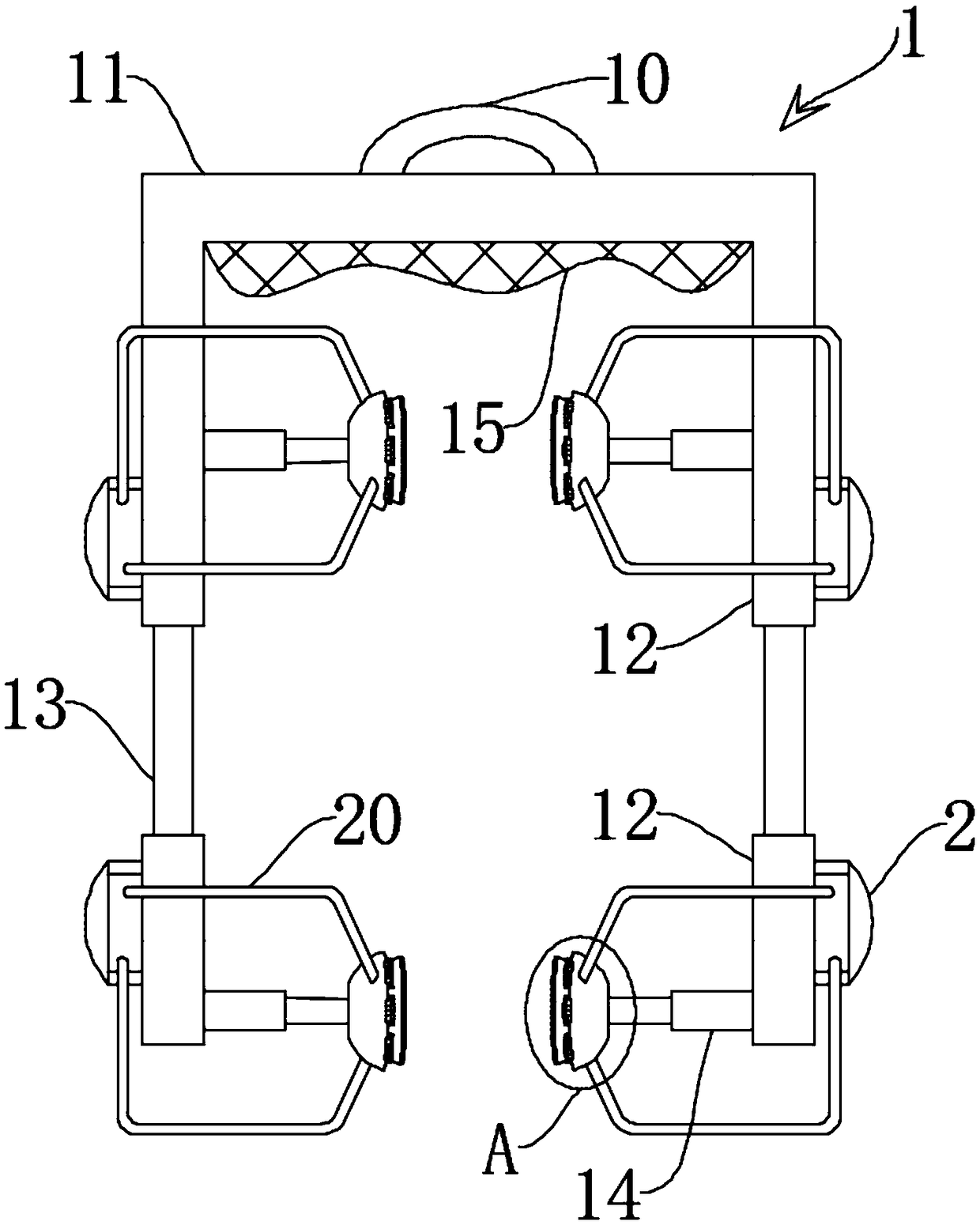
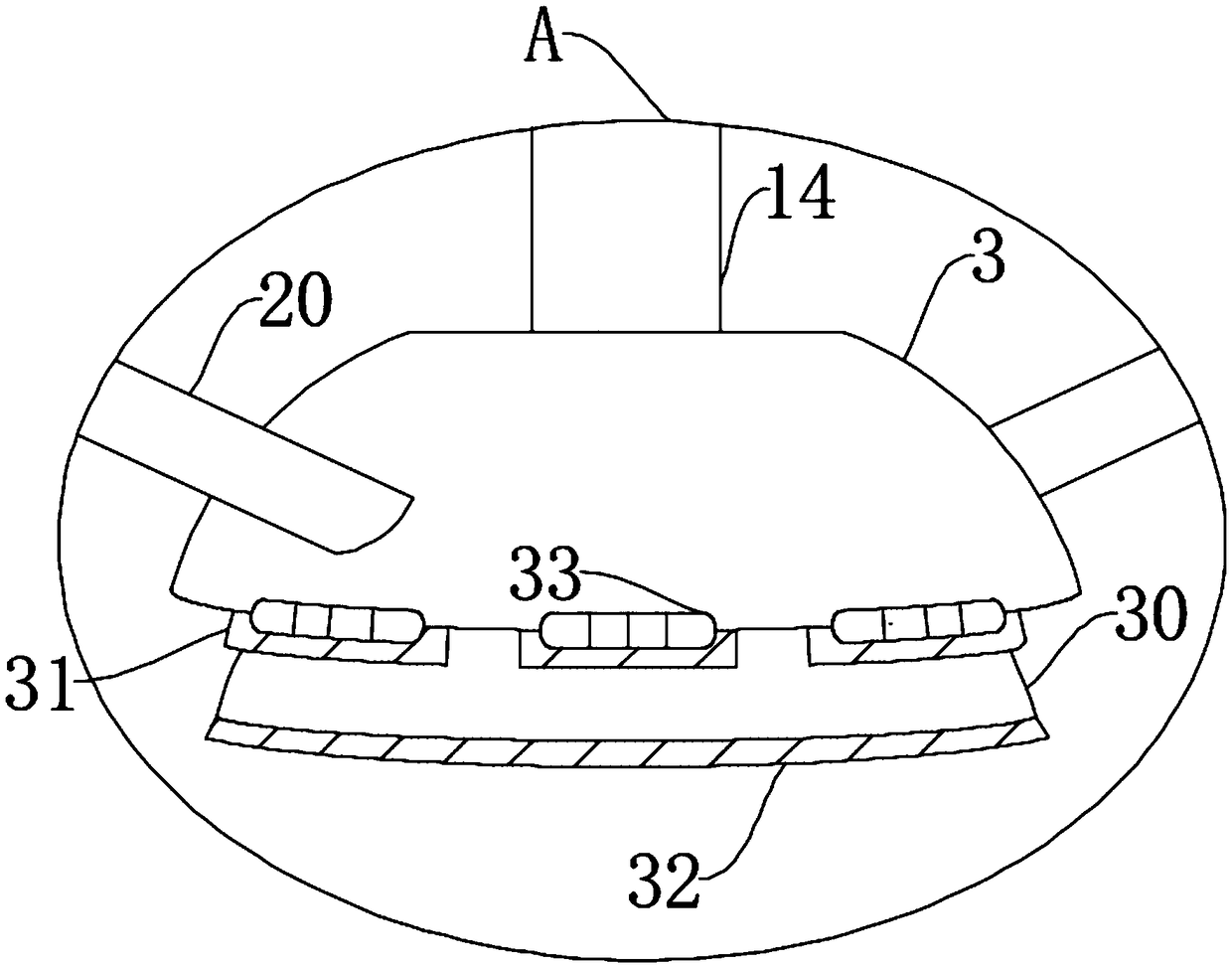
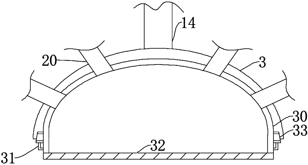
[0015] see Figure 1-3 , the present invention provides a technical solution: a quick clamping and hoisting device for electromechanical equipment, including a hoisting device 1, the hoisting device 1 is in the shape of a "U" frame with the opening facing downward, and it includes a fixed lifting ring 10, a bearing frame 11. The movable plate 12 and the pressurized fixing device, the fixed suspension ring 10 is arranged on the upper end of the bearing frame 11...


PUM


Abstract

The invention discloses rapid clamping and lifting equipment for motor equipment. The rapid clamping and lifting equipment comprises lifting equipment, two groups of two pairs of fixing blocks are oppositely arranged on a bearing framework, two fixing blocks in each group always keep parallel, a buffer block is fixed on the inner wall, facing the fixing block, of the bearing framework, the four fixing blocks adsorb and clamp the motor equipment from two directions when the novel structure is used, a buffer air bag is also adsorbed and clamped; the fixing blocks and the buffer air bag are arranged in a disc shape, the minimum diameter of the fixing block is equal to the maximal diameter of the buffer air bag, the fixing block and the buffer air bag are fixedly connected, the lower end faceof an antislip friction block and a limiting block are always on the same horizontal plane, the limiting block inclines outside on the basis of the buffer air bag, the buffer air bag and the fixing block adsorb and clamp a product stably when the structure works, the cushioning between the buffer air bag and a contact surface of the motor equipment is good, and the airtightness is better.

Description

technical field [0001] The invention relates to the related technical field of clamping and hoisting of electromechanical equipment, in particular to a quick clamping and hoisting equipment of electromechanical equipment. Background technique [0002] Generally speaking, electromechanical equipment refers to the sum of mechanical and electrical equipment. With the advancement of science and technology, the varieties of electromechanical equipment in the traditional sense have developed greatly. The general concept of electromechanical equipment in modern technology and management refers to mechanical products, electrical products, electronic products and mechatronic products, as well as parts, accessories, accessories, etc. of these products. It has gradually formed and is a conventional concept, and electromechanical equipment generally refers to large-scale production equipment with electric control, basically no production industry in design, such as: lathes, milling mach...

Claims


Application Information

Patent Timeline
IPC IPC(8): B66C1/42
CPCB66C1/42
Inventor 胡正翠
Owner 苏州睿鑫莱机电科技有限公司
Learn More