Steel bar truss plate end connecting joint structure and construction method thereof

A technology for steel truss and connecting nodes, which is applied to truss structures, truss beams, floor slabs, etc., can solve the problems of difficult lifting and transportation of steel grid composite formwork, complicated installation nodes, weak load-bearing capacity, etc., and achieves good earthquake resistance and impact resistance. , Improve construction efficiency and reduce the effect of construction period

Pending Publication Date: 2018-10-09
ZHE JIANG ZHONGYI BUILDING MATERIALS TECH CO LTD
View PDF9 Cites 4 Cited by
  • Summary
  • Abstract
  • Description
  • Claims
  • Application Information

AI Technical Summary

Problems solved by technology

The formwork can be reused, the cost is reduced, and the secondary decoration is convenient. However, it can only be applied to the frame beam structure, and it is rarely used on the steel structure beam. Moreover, it is difficult to lift the formwork of the reinforced grid structure, and the large-area The installation nodes of the composite formwork of the reinforced grid frame are complicated, the connection strength is low, and the load-bearing capacity is weak

Method used


Image

  • Steel bar truss plate end connecting joint structure and construction method thereof
  • Steel bar truss plate end connecting joint structure and construction method thereof
  • Steel bar truss plate end connecting joint structure and construction method thereof

Examples


Embodiment 1

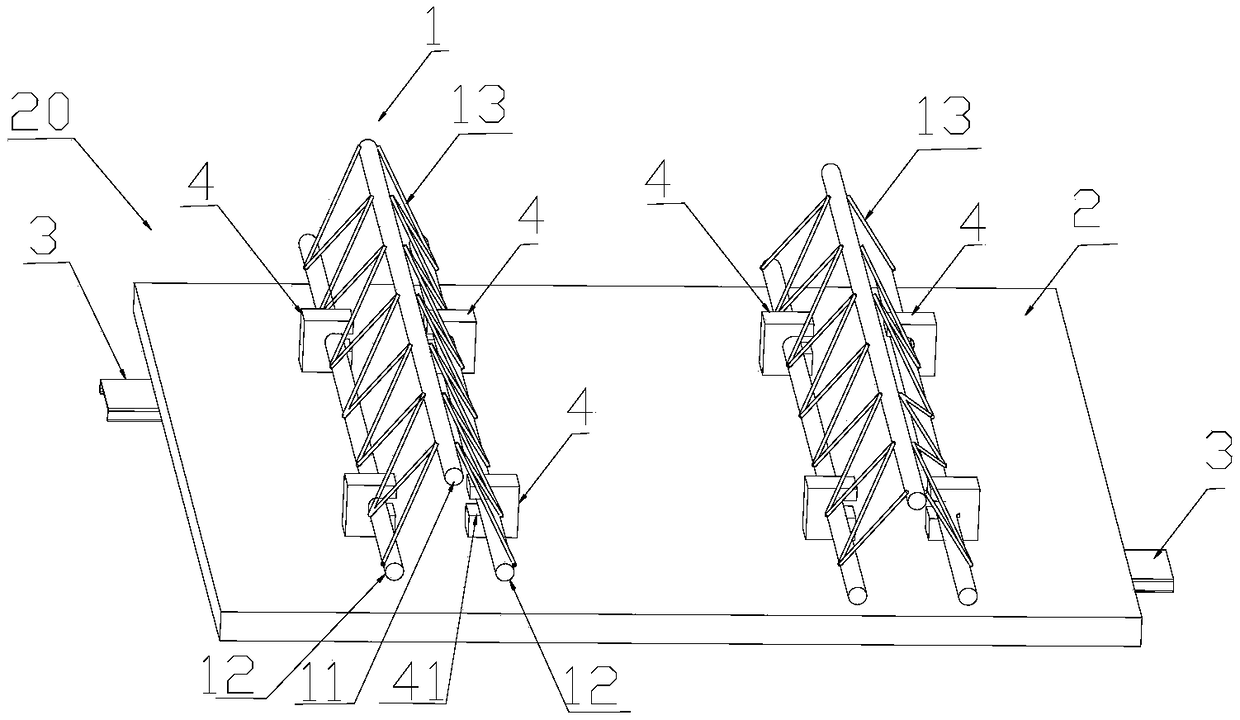
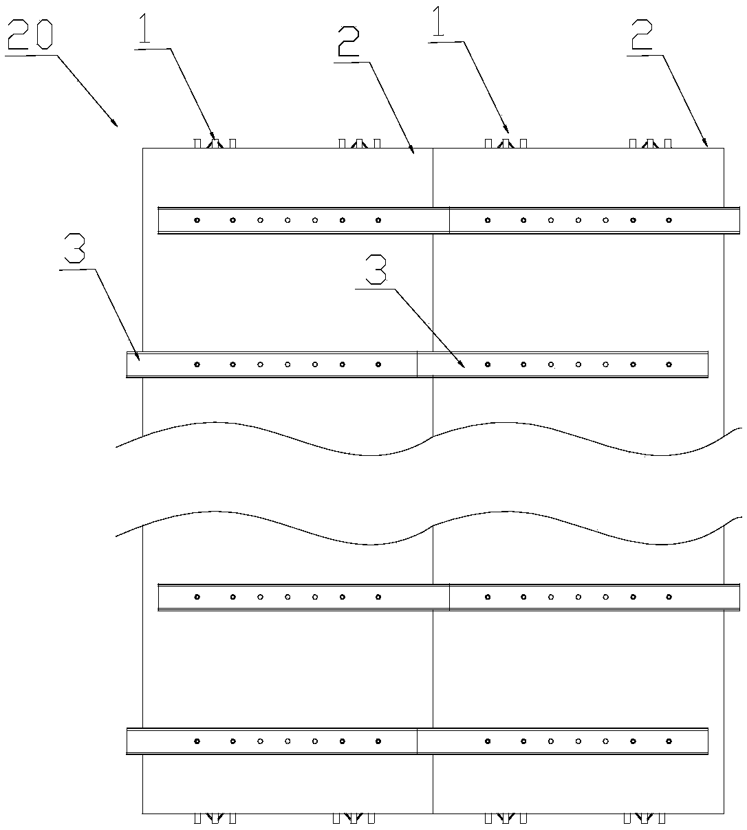
[0035] like figure 1 , figure 2 A detachable steel truss slab 20 is shown, which includes a steel truss 1 , a connecting piece 4 , a floor deck 2 and a supporting piece 3 . The steel bar truss 1 includes an upper chord steel bar 11 and two lower chord steel bars 12 , and the two lower chord steel bars 12 are respectively welded and connected to the upper chord steel bars 11 through web steel bars 13 . The two lower chord steel bars 12 are connected with the connecting piece 4 relative to each other. The connecting piece 4 includes a slot 41 through the connecting piece 4 with a side opening, and a threaded hole is provided at the lower end of the connecting piece 4 . The connectors 4 are clamped on the two lower chord steel bars 12 in pairs, and each pair of connectors 4 is arranged longitudinally on the steel bar truss 1 .

[0036] figure 1 The span of the shown detachable steel truss slab 20 can be designed according to requirements, generally 1-3m, and its width is two...


PUM


Abstract

The invention relates to the field of construction of steel structure buildings, in particular to a steel bar truss plate end connecting joint structure and a construction method thereof. The steel bar truss plate end connecting joint structure comprises steel bar truss plates and steel structure beams; one side of each floor bearing plate is detachably connected with a steel bar truss, and supporting pieces are arranged on the other sides of the floor bearing plates at intervals and stretch out of the floor bearing plates; a steel bar truss plate is laid on one side of each steel structure beam; and supporting bars are welded to the ends of the steel bar trusses and welded to the steel structure beams, and the upper surfaces of the floor bearing plates and the overlapping surfaces, connected to the steel structure beams in an overlapping mode, of the steel bar trusses are equivalent in height. According to the steel bar truss plate end connecting joint structure and the construction method thereof, the detachable steel bar truss plates are assembled at a small area on site, thus hoisting and assembling of the steel bar truss plates are convenient and easy, the single steel bar truss plate can be welded and fixed after being assembled, the adjacent steel bar truss plates are mutually supported through the supporting pieces, thus the dislocation gaps of the steel bar truss plates are reduced, and a floor surface is flat and can be directly whitewashed, mounted and dismounted.

Description

technical field [0001] The invention relates to the field of concrete structure building construction, in particular to a connection node structure and a construction method at the ends of steel bar truss plates. Background technique [0002] At present, horizontal structural formwork projects in my country's construction industry generally adopt bent frame support, supplemented by wooden squares and plywood or formwork. Its technological principle provides support for the floor slab by setting up a bent support system to meet the bearing capacity and deformation requirements during the construction stage. Due to the cumbersome and complicated process of the bent support system, foundation treatment, erection of scaffolding, installation of formwork, binding of steel bars, concrete pouring, maintenance, and formwork removal will take up a lot of time and construction period, and the rental management cost of scaffolding is high. Hazards of working at heights. [0003] In r...

Claims


Application Information

Patent Timeline
Patent Type & Authority Applications(China)
IPC IPC(8): E04B1/38E04C3/02E04C3/04E04B5/16
CPCE04B1/38E04B5/16E04C3/02E04C3/04
Inventor 陈永德叶健
Owner ZHE JIANG ZHONGYI BUILDING MATERIALS TECH CO LTD
Why Eureka
Try Eureka