End supporting joint structure and construction method of detachable steel bar truss plate

A technology of reinforced trusses and supporting nodes, which is applied in the direction of floors, building components, building structures, etc., can solve the problems of heavy steel grid truss combined formwork, high processing accuracy requirements, complex installation nodes, etc., and achieve simple and easy splicing and dismantling Good operation, anti-seismic and impact resistance, efficient and fast laying effect

Pending Publication Date: 2018-10-09
ZHE JIANG ZHONGYI BUILDING MATERIALS TECH CO LTD
View PDF10 Cites 3 Cited by
  • Summary
  • Abstract
  • Description
  • Claims
  • Application Information

AI Technical Summary

Problems solved by technology

[0004] The above-mentioned self-supporting steel grid frame combination formwork occupies a large space when the grid frame and formwork are assembled and produced, the production efficiency is low, and the handling is not convenient, and the processing accuracy is high; at the same time, there are the following problems during construction: the steel grid frame combination formwork The weight is too large to be transported manually, and the tower crane needs to be occupied for a long time; the combined formwork of the steel grid frame has a large area and there are great safety hazards when hoisting, and the laying difficulty is high and the efficiency is low
Therefore, the installation nodes of the existing reinforced grid combined formwork are complicated, the connection strength is low, and the load-bearing capacity is weak; in addition, supports and stabilizing braces need to be set separately to stabilize the overall formwork, and the construction efficiency is low

Method used


Image

  • End supporting joint structure and construction method of detachable steel bar truss plate
  • End supporting joint structure and construction method of detachable steel bar truss plate
  • End supporting joint structure and construction method of detachable steel bar truss plate

Examples


Embodiment 1

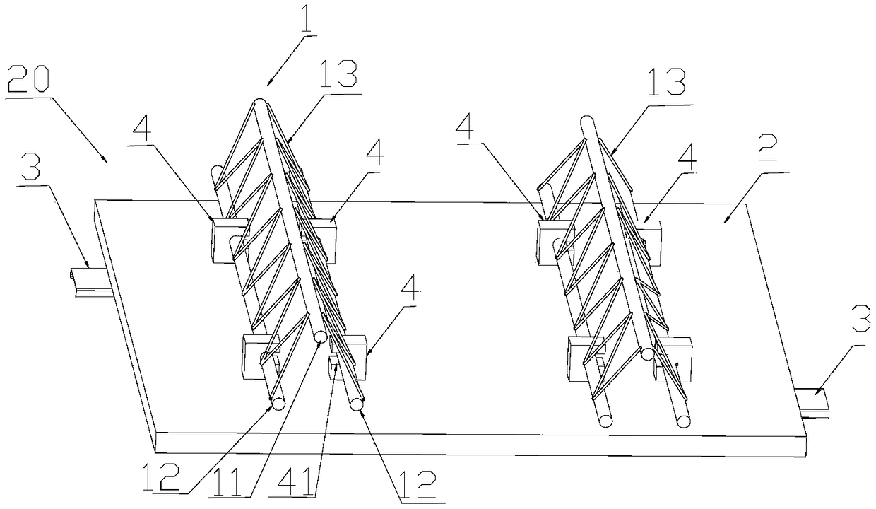
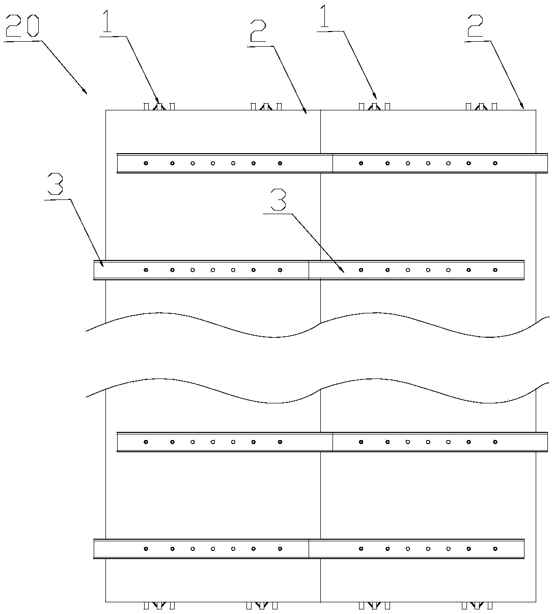
[0047] Such as figure 1 , figure 2A detachable steel truss slab 20 is shown, which includes a steel truss 1 , a connecting piece 4 , a floor deck 2 and a supporting piece 3 . The steel bar truss 1 includes an upper chord steel bar 11 and two lower chord steel bars 12 , and the two lower chord steel bars 12 are respectively welded and connected to the upper chord steel bars 11 through web steel bars 13 . The two lower chord steel bars 12 are connected with the connecting piece 4 relative to each other. The connecting piece 4 includes a slot 41 through the connecting piece 4 with a side opening, and a threaded hole is provided at the lower end of the connecting piece 4 . The connectors 4 are clamped on the two lower chord steel bars 12 in pairs, and each pair of connectors 4 is arranged longitudinally on the steel bar truss 1 .

[0048] figure 1 The span of the shown detachable steel truss slab 20 can be designed according to requirements, generally 1-3m, and its width is t...

Embodiment 2

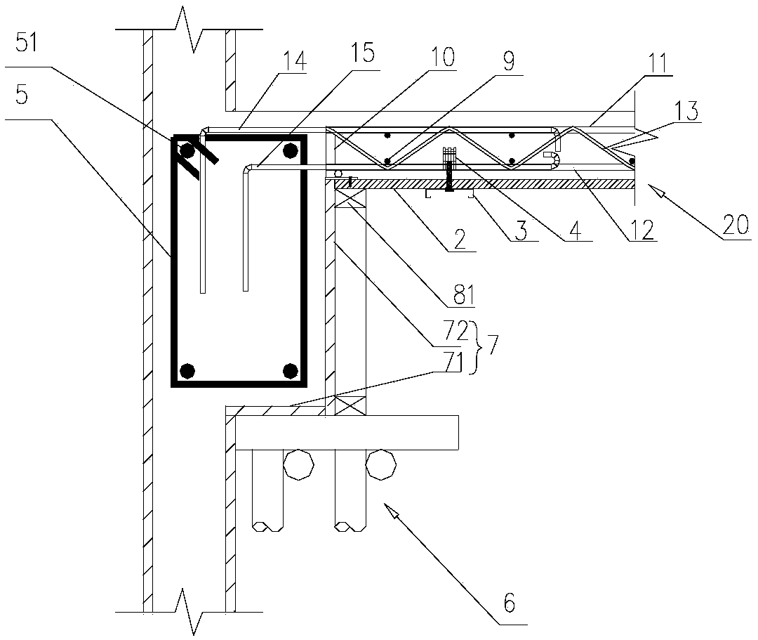
[0080] Such as Figure 7As shown, the difference between this embodiment and Embodiment 1 is that the frame structure 5 is a frame structure wall, so the frame structure 5 does not need a support frame to support it, and the frame structure 5 is provided with a frame formwork 7, so The outer side of the frame template 7 is erected with a first support member 81 , and the upper end of the first support member 81 is in contact with the steel bar truss plate 20 . The ends of the anchor bars 14 and 15 are bent and extend into the frame structure 5 .

Embodiment 3

[0082] Such as Figure 11 As shown, the difference between this embodiment and the above-mentioned embodiment is that steel bar truss plates 20 are respectively arranged on both sides of the frame structure 5, and the steel bar truss plates 20 on both sides of the frame structure 5 are respectively provided with anchor ribs 14A, 15A, and anchored Ribs 14B, 15B. The anchor ribs 14B, 15B are located between the upper and lower ribs 51 of the frame structure 5 .


PUM


Abstract

The invention relates to the field of concrete structure building construction, in particular to an end supporting joint structure of a detachable steel bar truss plate. The end supporting joint structure comprises the steel bar truss plate, a frame structure and a first supporting piece. The steel bar truss plate comprises a floor bearing plate and a steel bar truss detachably connected to one side of the floor bearing plate. A frame formwork is arranged on the outer side of the frame structure and comprises a side formwork, the floor bearing plate is arranged on one side of the side formwork, and the upper end of the side formwork and the upper surface of the floor bearing plate are equivalent in height. The first supporting piece is provided with the end for supporting the steel bar truss plate. The ends of the side formwork and the floor bearing plate mutually abut or are arranged in a clearance mode, thus splicing and dismantling of the side formwork and the floor bearing plate are easy and easy to operate, slurry is not prone to leaking, the formed floor face and the beam face or a wall face are good in transition, the pour-formed floor face is good in integrity, shock and impact resistance and waterproofness, and the floor face is level and can be directly whitewashed, assembled and disassembled.

Description

technical field [0001] The invention relates to the field of concrete structure building construction, in particular to a detachable reinforced truss slab end support node structure and a construction method. Background technique [0002] At present, horizontal structural formwork engineering in my country's construction industry generally adopts the method of erecting bent frame supports, supplementary wooden squares and plywood or formwork. Its technological principle provides support for the bottom formwork by setting up a bent support system to meet the requirements of bearing capacity and deformation during the construction stage. [0003] Chinese patent: CN103352563, patent name: self-supporting steel grid frame composite formwork and its construction method, discloses a steel grid frame composed of multiple rows of longitudinal steel trusses and multiple rows of horizontally distributed steel bars, and the combination of steel grid frame and detachable formwork Reali...

Claims


Application Information

Patent Timeline
Patent Type & Authority Applications(China)
IPC IPC(8): E04B1/38E04B5/16E04G11/48
CPCE04B1/38E04B5/16E04G11/48
Inventor 陈永德叶健
Owner ZHE JIANG ZHONGYI BUILDING MATERIALS TECH CO LTD
Why Eureka
Try Eureka