
Interconnected radiating device and light-emitting diode (LED) lamp using same

A technology of LED lighting and heat dissipation device, which is applied in the field of machinery, can solve the problems of affecting the working performance of LED lamps, wasting the heat dissipation function of radiators, and the lack of maintenance of radiators, etc., so as to improve production efficiency and output, and achieve better heat dissipation effects. The effect of reducing the production cost

Active Publication Date: 2014-10-15
DONGGUAN WENYU IND
View PDF5 Cites 5 Cited by
  • Summary
  • Abstract
  • Description
  • Claims
  • Application Information

AI Technical Summary

Problems solved by technology

If the radiator cannot be disassembled, assembled and deformed by itself, when the heat increases, the heat will not be dissipated in time, which will affect the normal working performance of the LED lamp, and even cause the LED lamp to overheat and be damaged. When the heat decreases, it will The heat dissipation function of part of the radiator is wasted. Therefore, in view of the above problems, there is an urgent need for a radiator that can be disassembled, assembled and deformed by itself
[0005] In addition, it will be extremely inconvenient for the overall assembly and partial maintenance of the radiator, resulting in some radiators being discarded due to minor faults without maintenance, resulting in great waste

Method used


Image

  • Interconnected radiating device and light-emitting diode (LED) lamp using same
  • Interconnected radiating device and light-emitting diode (LED) lamp using same
  • Interconnected radiating device and light-emitting diode (LED) lamp using same

Examples


Embodiment Construction

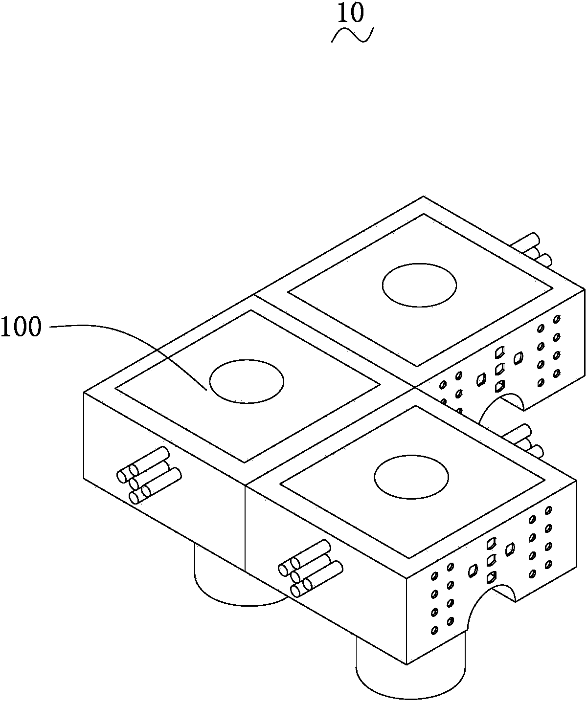
[0036] like figure 1 As shown, it is a structural diagram of splicing interconnected cooling devices 10 according to a preferred embodiment of the present invention.

[0037] The interconnected cooling device 10 includes several cooling units 100 . A plurality of cooling units 100 are spliced ​​with each other.

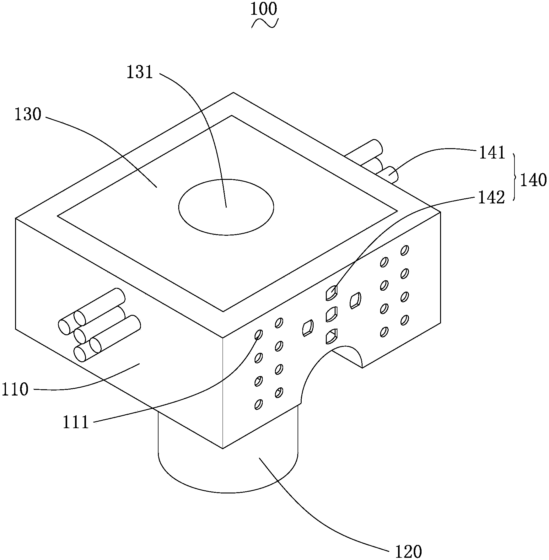
[0038] Please also refer to figure 2 , which is figure 1 A schematic structural diagram of the heat dissipation unit 100 of the interconnected heat dissipation device 10 is shown.

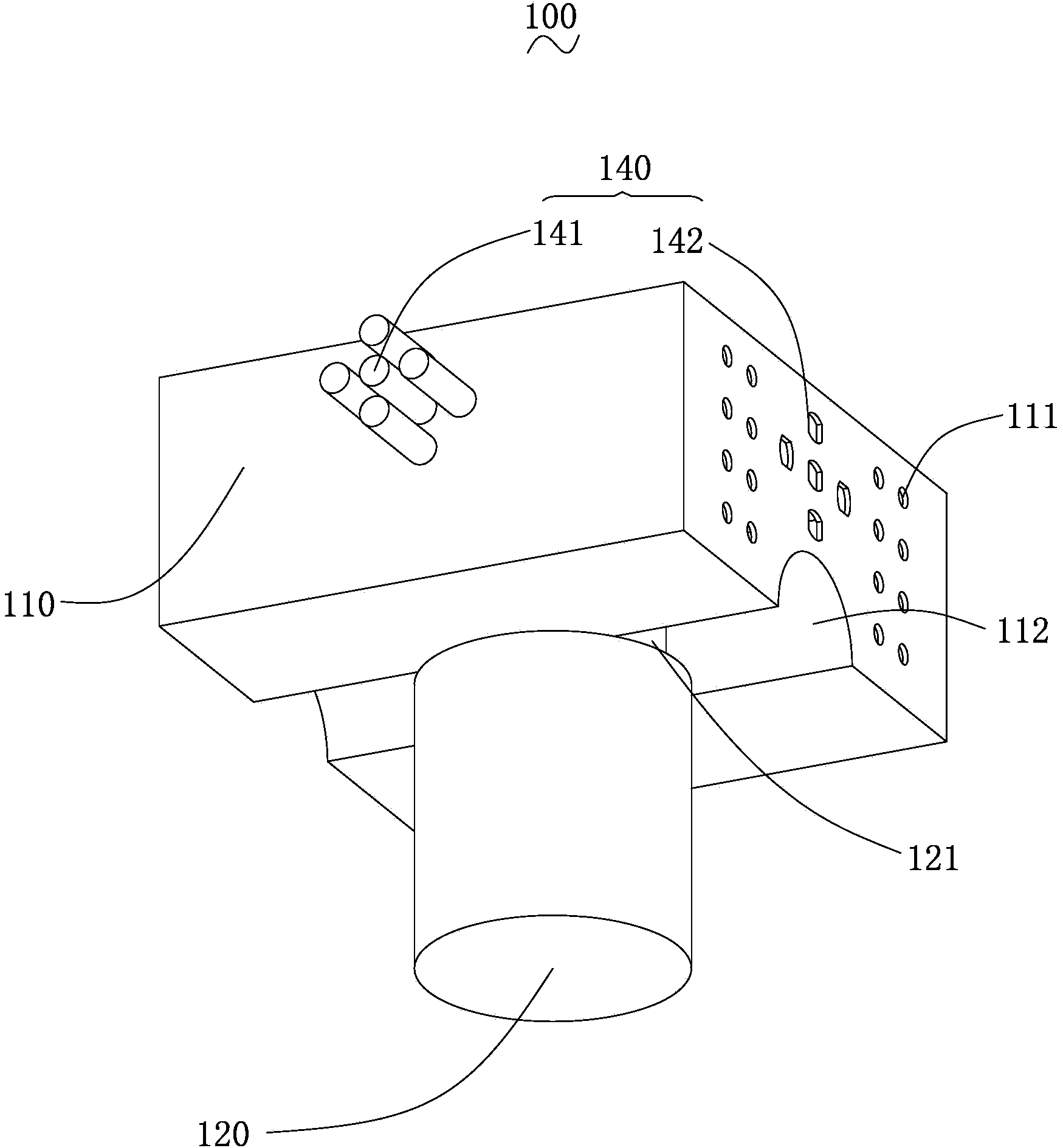
[0039] Each cooling unit 100 includes a mounting frame 110 , a mounting seat 120 , a mounting plate 130 and an interconnection component 140 . The mounting seat 120 is disposed on the lower surface of the mounting frame 110 for mounting the LED lighting unit. The mounting plate 130 is disposed at a position where the lower surface of the mounting frame 110 is opposite to the upper surface, and the mounting plate 130 is provided with a mounting position 131 for mounting on the lamp ho...


PUM

PropertyMeasurementUnit
Lengthaaaaaaaaaa

Abstract

The invention relates to an interconnected radiating device and a light-emitting diode (LED) lamp using the same. The interconnected radiating device comprises a plurality of radiating units. Each radiating unit comprises an installation frame and an installation plate, the installation frame is a hollow cuboid frame, an installation seat is arranged on the lower surface of the installation frame and used for installing an LED lighting unit, the installation plate is arranged on the upper surface of the installation frame opposite to the lower surface, an installation position is arranged on the installation plate and used for installing the installation plate on a lamp holder, at least one of two pairs of sides between the upper surface and the lower surface is provided with an interconnected assembly, the interconnected assembly comprises an insertion connection portion group and an insertion connection position group, the insertion connection position group is used for inserting the insertion connection portion group of another radiating unit, and the insertion connection portion group is inserted into the insertion connection position group of another radiating unit. The length of the insertion connection portion group inserted into the insertion connection position group is larger than 1cm. The insertion connection position group is provided with a plurality of insertion connection positions correspondingly, and the plurality of insertion connection positions are inserted into the insertion connection portions in a one-to-one correspondence mode. The interconnected radiating device fully utilizes space and is better in radiating effect.

Description

technical field [0001] The invention relates to the mechanical field, in particular to a heat dissipation device and an LED lighting lamp using the heat dissipation device. Background technique [0002] LED (Light Emitting Diode, Light Emitting Diode), which can directly and efficiently convert electrical energy into visible light, and has a service life of tens of thousands of hours to 100,000 hours. Widely used in landscape, security, special and general lighting and other fields, the market potential is immeasurable. [0003] LED lamps are known as the most commonly used lighting lamps for their high quality, durability, and energy-saving advantages. However, in the current LED lamps, the main heat dissipation function is the radiator. The heat generated by the LED lamp during operation is transferred to the radiator, and the heat is further transferred to the outside air through the radiator, and then the heat is dissipated. To ensure that the LED lights can continue t...

Claims


Application Information

Patent Timeline
IPC IPC(8): F21V29/00F21Y101/02
Inventor 叶伟炳
Owner DONGGUAN WENYU IND
Learn More