Friction type retarder

A retarder and friction-type technology, which is applied to transmission parts, belts/chains/gears, mechanical equipment, etc., can solve the problems of affecting the use effect, high cost, and inconvenient promotion and application of retarders.

Inactive Publication Date: 2018-10-09
孟志广
View PDF0 Cites 0 Cited by
  • Summary
  • Abstract
  • Description
  • Claims
  • Application Information

AI Technical Summary

Problems solved by technology

These two products both have the disadvantage of high cost, and will generate a lot of heat during use, seriously affecting the use effect, which brings great inconvenience to the popularization and application of the retarder

Method used


Image

  • Friction type retarder
  • Friction type retarder
  • Friction type retarder

Examples


Embodiment 1

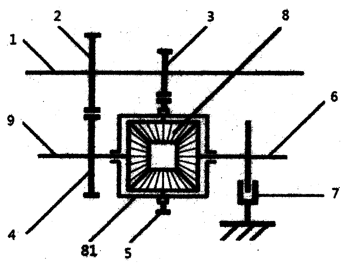
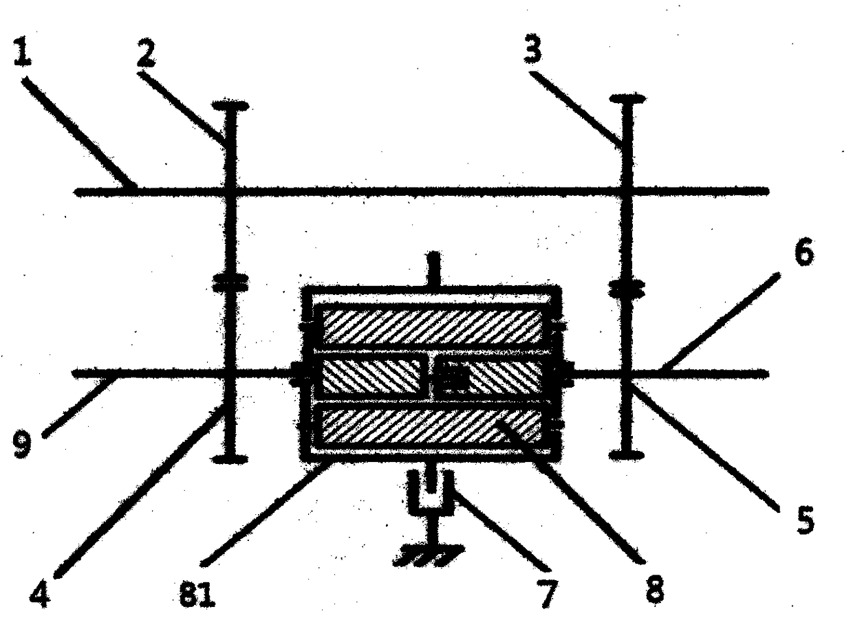
[0019] Example 1, see figure 1 , a friction retarder, including a main shaft, a planetary gear train with three connecting ends and a friction brake pair, gears (2), (3) are fixedly installed on the main shaft (1), gears (2), (3 ) meshes with the fixedly installed gears (4) and (5) on any two connecting ends of the planetary gear train, and through the setting of the transmission ratio between the gear pairs, the third connecting end of the planetary gear train is relative to the main shaft (1 ) to do deceleration rotation, and a friction pair (7) is installed on the third connection end.

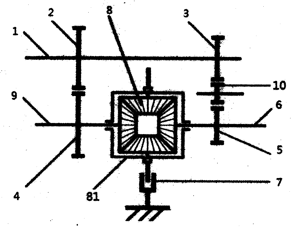
[0020] figure 2 , image 3 , Figure 4 Both are figure 1 deformation structure, where figure 2 In the structure, need to add an idler wheel (10) between gear (3) and gear (5).

Embodiment 2

[0021] Example 2, see Figure 5 , a friction retarder, including a main shaft, a planetary gear train with three connecting ends and a friction brake pair, a gear (2) is fixedly installed on the main shaft (1), and any one of the gear (2) and the planetary gear train The gear (5) fixedly installed on the connection end meshes, the gear (5) meshes with the gear (3), the gear (3) and the gear (11) are fixedly installed on the shaft (12), the gear (11) and the planetary gear train The gear (4) fixedly installed on the second connection end meshes, and the third connection end of the planetary gear train is decelerated relative to the main shaft (1) through the setting of the transmission ratio between the gear pairs, and on the third connection end A friction pair (7) is installed.

[0022] Image 6 , Figure 7 Yes Figure 5 The deformed structure, this structure is also suitable for such as image 3 , Figure 4 planetary gear train shown, but in image 3 In the structure ...

Embodiment 3

[0023] Embodiment three, see Figure 8 , in this embodiment, the axis (13) is used as the retarder control target axis, and the retarder control target axis (13) is connected with the main shaft (1) in the retarder through the gear (14), and the gear (14) Can be connected on any gear on the main shaft (1), and can install clutch (15) additionally on gear (14), on the gear that clutch also can be installed and the meshing of connecting gear (14). When the clutch is disengaged, the cooperating gear can rotate freely around the shaft; when the clutch is engaged, the cooperating gear and the shaft rotate synchronously.

[0024] The friction pair is one or more groups.

[0025] Described gear transmission also can replace with sprocket wheel and chain transmission.

[0026] The friction pair is caliper-brake disc or friction disc-brake disc or brake shoe-brake drum or friction cone-cone ring brake drum.

[0027] The retarders can be used alone or in combination. When used in com...


PUM


Abstract

The invention discloses a friction type retarder. The friction type retarder comprises a main shaft, a planetary gear train with three connecting ends and a friction type brake pair; two gears are fixedly installed on the main shaft, and the two gears are meshed with gears fixedly installed on any two connecting ends of the planetary gear train respectively; and through the transmission ratio between gear pairs or the setting of idle wheels, the third connecting end of the planetary gear train performs deceleration rotation relative to the main shaft, and the third connecting end is provided with the friction pair.

Description

technical field [0001] The invention relates to a retarder, in particular to a friction retarder. Background technique [0002] The retarders currently used on heavy vehicles are generally hydraulic retarders or electromagnetic retarders. These two kinds of products all have the deficiency of high cost, and can generate relatively large heat during use, seriously affect the use effect, and this brings great inconvenience to popularization and application of retarder. Contents of the invention [0003] Aiming at the above-mentioned deficiencies in the prior art, the object of the present invention is to provide a device that reduces the rotational speed in a large proportion, increases or does not increase the torque in a small proportion, and can generate a friction retarder with relatively low heat during the control process. [0004] For realizing the purpose of the present invention, adopt following technical scheme: [0005] A friction retarder, including a main shaf...

Claims


Application Information

Patent Timeline
Patent Type & Authority Applications(China)
IPC IPC(8): F16H37/08F16H57/08
CPCF16H37/08F16H57/08F16H2057/087
Inventor 孟志广
Owner 孟志广
Why Eureka
Try Eureka