flow control valve

A flow regulating valve, high flow technology, applied in high-efficiency regulation technology, valve lift, valve device, etc., can solve problems such as noise, pressure loss increase, obstruction of fluid flow, etc., to reduce noise, improve controllability, and suppress pressure loss effect

Active Publication Date: 2021-09-28
FUJIKOKI MFG CO LTD
View PDF14 Cites 0 Cited by
  • Summary
  • Abstract
  • Description
  • Claims
  • Application Information

AI Technical Summary

Problems solved by technology

[0003] However, when the flow regulating valve with the above-mentioned structure is combined with, for example, a heat pump cooling and heating system, there is a problem that the valve port is opened to a predetermined opening degree, and the refrigerant flowing into the valve chamber is released from the valve chamber. When flowing out through the gap formed between the valve core and the valve port, it is easy to generate continuous noise (fluid passing sound)
However, the noise reduction member is fixed to the valve main body in such a way that the inlet side and the outlet side of the valve chamber are always separated, so there is a problem that the flow of the flow through the valve port needs to be ensured in the large opening area, and the flow rate is blocked. Flowing to the valve port, the pressure loss (pressure loss) increases, and it is difficult to obtain an appropriate refrigerant flow rate
[0015] In addition, in this kind of flow regulating valve, in recent years, it is required to improve the controllability in the small opening area (low flow area), but if it is desired to ensure the controllability in the small opening area while solving the above-mentioned problems, then There are concerns about increasing the size, complicating the structure, and increasing the cost

Method used


Image

  • flow control valve
  • flow control valve
  • flow control valve

Examples


Embodiment Construction

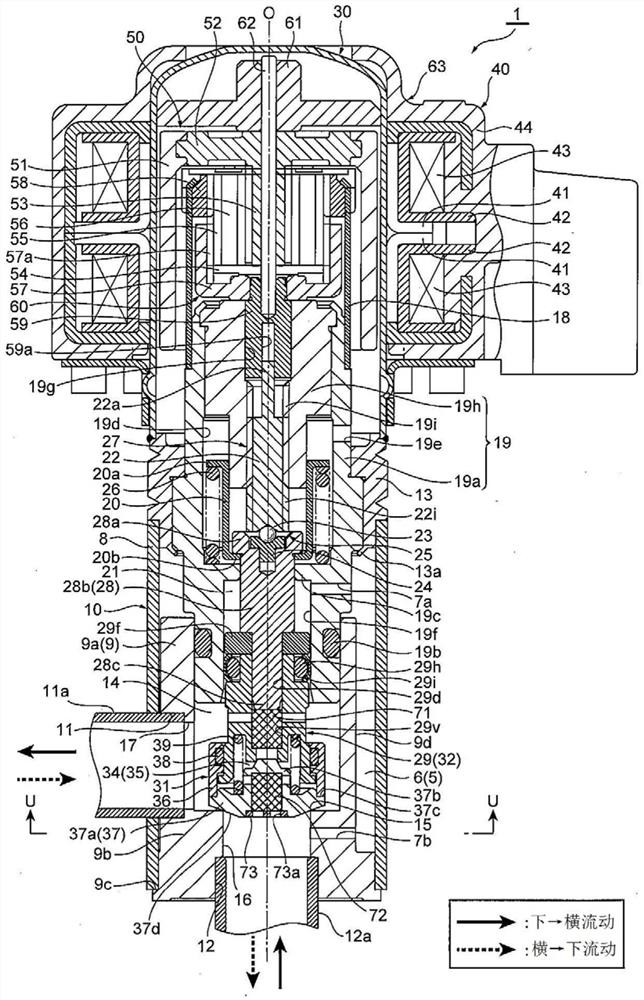
[0100] Below, while referring to the attached Figure 1 Embodiments of the present invention will be described.

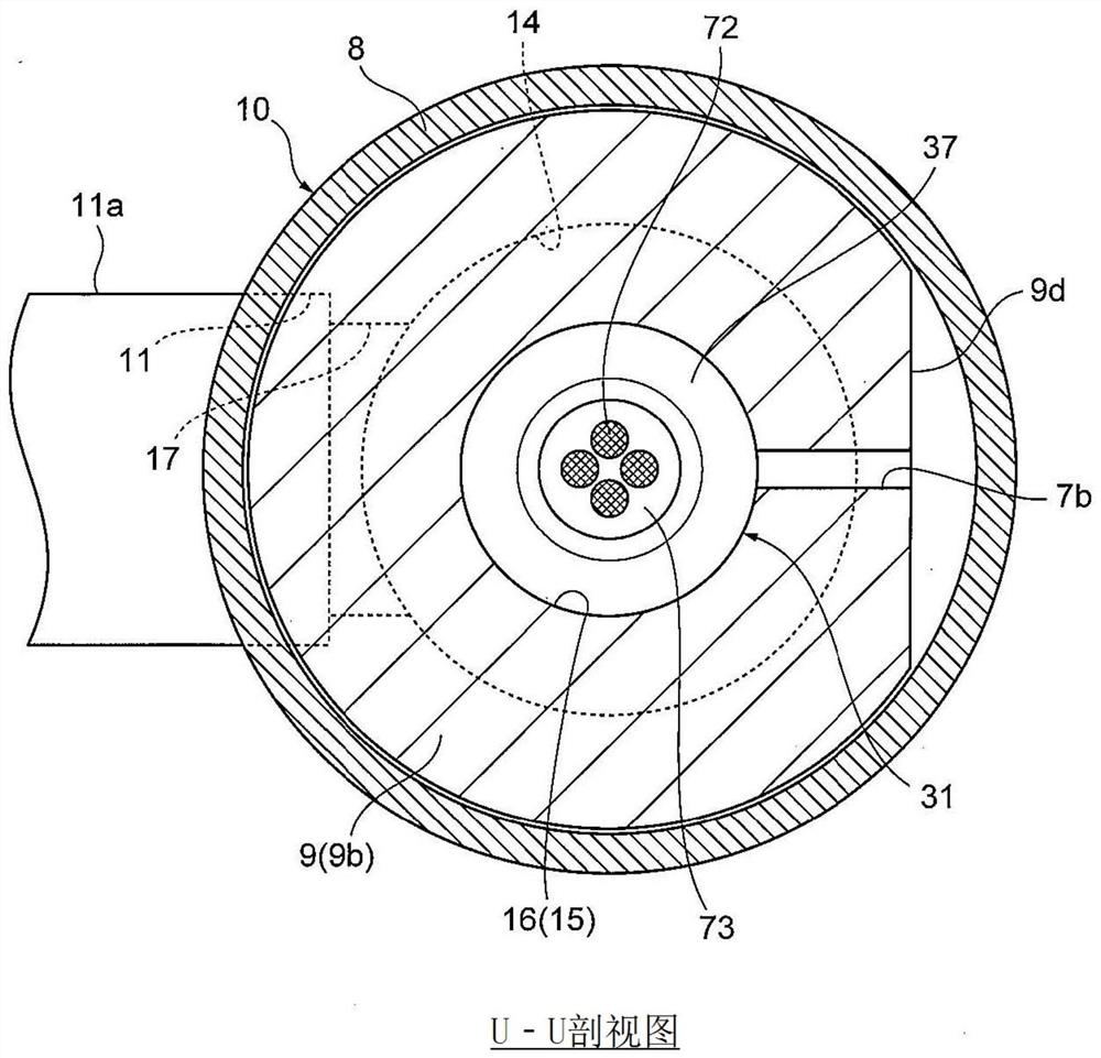
[0101] figure 1 is an overall cross-sectional view showing one embodiment of the flow control valve of the present invention, figure 2 yes figure 1 U-U direction sectional view of .

[0102] In addition, in this specification, descriptions indicating positions and directions such as up and down, left and right, and front and rear are added for the convenience of the drawings in order to avoid complicating the description, and are not limited to the positions and directions in the actual use state. .

[0103] In addition, in each figure, there are cases where the gaps formed between components, the spacing distance between components, etc. are enlarged compared with the size of each component for easy understanding of the invention and for convenience in drawing. Or reduced to depict.

[0104] (Structure of Flow Control Valve 1)

[0105] The flow regulating ...


PUM


Abstract

To provide a flow regulating valve capable of effectively reducing noise when fluid (refrigerant) passes, and capable of reducing pressure loss in a large opening area and improving controllability in a small opening area with a simple structure. A small flow passage (35) connecting the valve chamber (14) and the valve port (16) for large flow through the upper communication passage (33a), the communication space (34) and the lower communication passage (33b) is formed. The fluid flow rate of the small flow valve port (29c) in the small flow passage changes according to the lift of the main spool (29). The opening area (A2) of the valve port and the pressure receiving area (A1) in the lifting direction of the auxiliary valve core (31) make the force acting on the valve closing direction of the auxiliary valve core in the valve opening direction under the small flow control state above the force.

Description

technical field [0001] The invention relates to a flow regulating valve suitable for regulating the flow of refrigerant in heat pump cooling and heating systems. Background technique [0002] As an example of such a flow regulating valve, there is known an electric valve comprising: a valve main body provided with a valve chamber and a valve port (orifice) with a valve seat; The amount of lift from the valve seat changes the flow rate of the fluid flowing through the valve port, and the valve core is moved in contact with, separated from, or close to the valve seat by a screw-feed type lifting drive mechanism as described in Patent Documents 1 to 3, for example. Lifting in a way away from it, the screw feed type lifting drive mechanism is composed of a valve shaft with external threads, a bearing component with internal threads, and a stepping motor. [0003] However, when the flow regulating valve with the above-mentioned structure is combined with, for example, a heat pum...

Claims


Application Information

Patent Timeline
Patent Type & Authority Patents(China)
IPC IPC(8): F16K31/04F16K27/02F16K31/53F16K47/02F25B41/31
CPCF16K27/02F16K31/046F16K31/53F16K47/02F25B41/30Y02B30/70F16K1/36F16K31/047F16K47/04F16K1/54
Inventor 柳泽秀原田贵雄大内共存
Owner FUJIKOKI MFG CO LTD
Why Eureka
Try Eureka