Spring resetting mechanism for electric actuator

A technology of spring return mechanism and electric actuator, applied in the direction of engine components, spring/shock absorber, coil spring, etc., can solve problems such as power failure, valve out of control, brake motor inoperability, etc., to reduce operational risks and facilitate installation Effect

Pending Publication Date: 2018-10-09
李伟
View PDF5 Cites 7 Cited by
  • Summary
  • Abstract
  • Description
  • Claims
  • Application Information

AI Technical Summary

Problems solved by technology

[0002] Actuators play a very important role in the automation of modern production processes, especially electric actuators, also known as electric actuators. It is the combination of electric actuator and valve to obtain valve electric device; the combination of brake motor and electric actuator can obtain angular travel electric actuator with high control precision; the brake motor of the above electric actuator is guided by brake power supply and motor power supply. However, in extreme cases, the electric actuator is faced with a complete power failure, and the brake motor cannot operate, causing the valve to be out of control. It is necessary to provide a valve reset device used in the case of power failure

Method used


Image

  • Spring resetting mechanism for electric actuator
  • Spring resetting mechanism for electric actuator

Examples


Embodiment 1

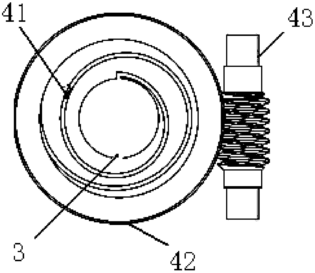
[0014] Such as figure 1 As shown, the spring return mechanism for the electric actuator of this embodiment includes a main shaft 3, a scroll spring 41, a turbine ring 42, and a worm screw 43 that cooperate with the valve stem for transmission. The main shaft 3 is sleeved in the scroll spring 41, and the scroll The spring 41 is sleeved in the turbine ring 42, the inner starting end of the scroll spring 41 is fixedly connected with the outer wall of the main shaft 3, the outer end of the scroll spring 41 is fixedly connected with the inner wall of the turbine ring 42, and the worm 43 is fixedly connected with the inner wall of the turbine ring 42. The outer sides of the ring 42 are meshed so that when the main shaft 3 rotates, the scroll spring 41 can be driven to store energy. When the worm 43 rotates, the turbine ring 42 can be driven to rotate to drive the scroll spring 41 to preload.

Embodiment 2

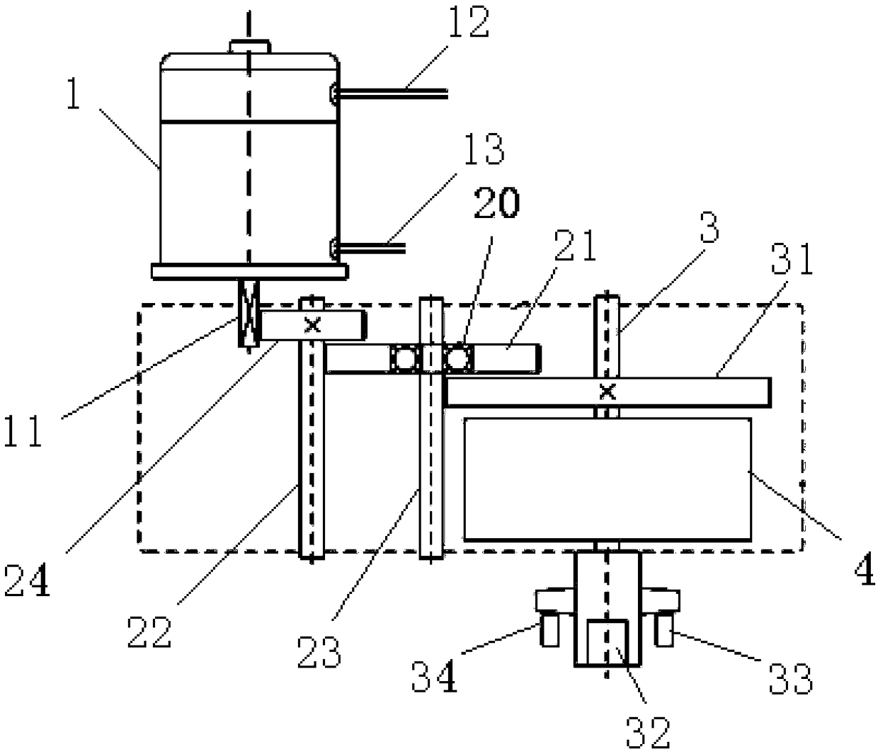
[0016] Such as figure 2 As shown, an electric actuator applying the spring return mechanism of Embodiment 1 includes a spring return mechanism 4 composed of a main shaft 3, a scroll spring 41, a turbine ring 42, and a worm 43, and also includes a brake motor 1, a one-way transmission mechanism, the one-way transmission mechanism includes a first transmission shaft 22, a second transmission shaft 23, a first gear 24, and an overrunning clutch. 23 through the one-way bearing 21 and the first transmission shaft 22 transmission and cooperation, and the first transmission shaft 22 is meshed with the outer ring 21 of the overrunning clutch 2, and the second transmission shaft 23 is fixedly connected with the inner ring 20 of the overrunning clutch 2, so that The brake motor 1 can drive the second drive shaft 23 to rotate; the spring return mechanism 4 also includes a second gear 31, a left limit bolt 34 and a right limit bolt 33 for limiting the rotation angle of the main shaft 3, ...


PUM


Abstract

The invention relates to a spring resetting mechanism for an electric actuator. The spring resetting mechanism for the electric actuator comprises a main shaft, a volute spiral spring and a turbine ring, wherein the main shaft, the volute spiral spring and the turbine ring are capable of driving a valve rod to rotate; the main shaft is arranged in the volute spiral spring in a sleeved mode, the volute spiral spring is arranged in the turbine ring in a sleeved mode, and the inner side starting end of the volute spiral spring is in transmission fit with the main shaft; and the outer side end ofthe volute spiral spring is in transmission fit with the inner side of the turbine ring, so that when the main shaft rotates, the volute spiral spring can be driven to rotate, energy storage is carried out, when the volute spiral spring is released, the main shaft can be driven to rotate in the reverse direction, so that the valve can be reset.

Description

technical field [0001] The invention relates to the technical field of auxiliary equipment for electric actuators, in particular to a spring return mechanism for electric actuators. Background technique [0002] Actuators play a very important role in the automation of modern production processes, especially electric actuators, also known as electric actuators. It is the combination of the electric actuator and the valve to obtain the valve electric device; the combination of the brake motor and the electric actuator can obtain the angular travel electric actuator with high control precision; However, in extreme cases, the electric actuator is faced with a complete power failure, and the brake motor cannot be operated, causing the valve to be out of control. It is necessary to provide a valve reset device used in the case of power failure. Contents of the invention [0003] The technical problem to be solved by the present invention is to provide a spring return mechanism...

Claims


Application Information

Patent Timeline
Patent Type & Authority Applications(China)
IPC IPC(8): F16K31/04F16K31/53F16F1/10
CPCF16F1/10F16K31/047F16K31/53
Inventor 李伟焦子靖
Owner 李伟
Why Eureka
Try Eureka