High pressure gas source-to-work piece inflating method, inflating device and differential pressure airtightness detector

A high-pressure gas source and inflatable device technology, which is used in liquid/vacuum measurement for liquid tightness, gas/liquid distribution and storage, and measurement of fluid acceleration and deceleration rates. The problem of high valve accuracy requirements, to achieve the effect of low production cost, reduce production cost, and realize air pressure control

Pending Publication Date: 2018-10-09
HANGZHOU GUHENG ENERGY SCI & TECH
View PDF0 Cites 6 Cited by
  • Summary
  • Abstract
  • Description
  • Claims
  • Application Information

AI Technical Summary

Problems solved by technology

[0006] The purpose of the present invention is to solve the problem that the differential pressure air tightness detector in the prior art requires high precision of the pressure regulating valve under the condition of small test air pressu

Method used


Image

  • High pressure gas source-to-work piece inflating method, inflating device and differential pressure airtightness detector
  • High pressure gas source-to-work piece inflating method, inflating device and differential pressure airtightness detector
  • High pressure gas source-to-work piece inflating method, inflating device and differential pressure airtightness detector

Examples


Embodiment 1

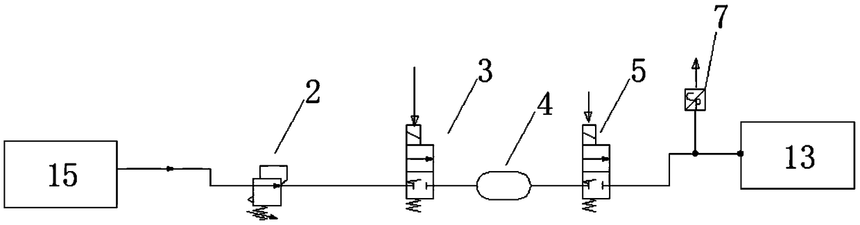
[0031] combined with figure 1 Shown, a kind of inflation method to workpiece by high-pressure gas source, it comprises the following steps:

[0032] (1) A first valve 3, an air tank 4 and a second valve 5 connected in sequence are arranged between the high-pressure gas source 15 and the workpiece 13;

[0033] (2) The first valve 3 is turned on, the second valve 5 is disconnected, and the high-pressure gas source 15 inflates the gas tank 4;

[0034] (3) The first valve 3 is disconnected, the second valve 5 is turned on, and the gas tank 4 inflates the workpiece 13;

[0035] (4) Steps (2) and (3) are repeated, and the first valve 3 and the second valve 5 are alternately turned on and off, so that the high-pressure gas source 15 inflates the workpiece 13 through the gas tank 4 to reach the preset air pressure.

[0036] In the step (2), a fine pressure regulating valve 2 is provided between the first valve 3 and the high-pressure gas source 15 , and the air pressure of the infla...

Embodiment 2

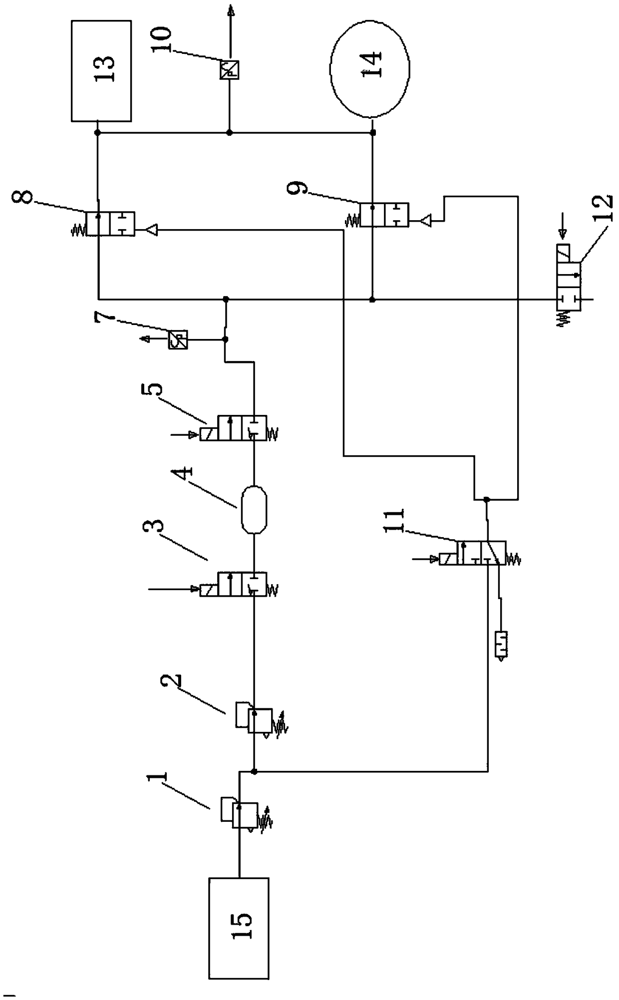
[0039] combined with figure 2 As shown, a differential pressure air tightness detector related to the present invention includes a high pressure gas source 15, a coarse pressure regulating valve 1, a fine pressure regulating valve 2, a buffer device, a pressure sensor 7, a first control valve 8, a second control valve valve 9 and differential pressure gauge 10. The buffer device further includes an air tank 4, and a first electromagnetic valve 3 and a second electromagnetic valve 5 arranged at the air inlet and exhaust ports of the air tank.

[0040]The air inlet of the coarse pressure regulating valve 1 is connected with the high-pressure gas source through the gas pipeline, the air inlet of the fine pressure regulating valve 2 is connected with the air outlet of the coarse pressure regulating valve 1 through the gas pipeline, and the air inlet of the first solenoid valve 3 Connect the air outlet of the fine pressure regulating valve 2 through the gas pipeline, the air inle...

Embodiment 3

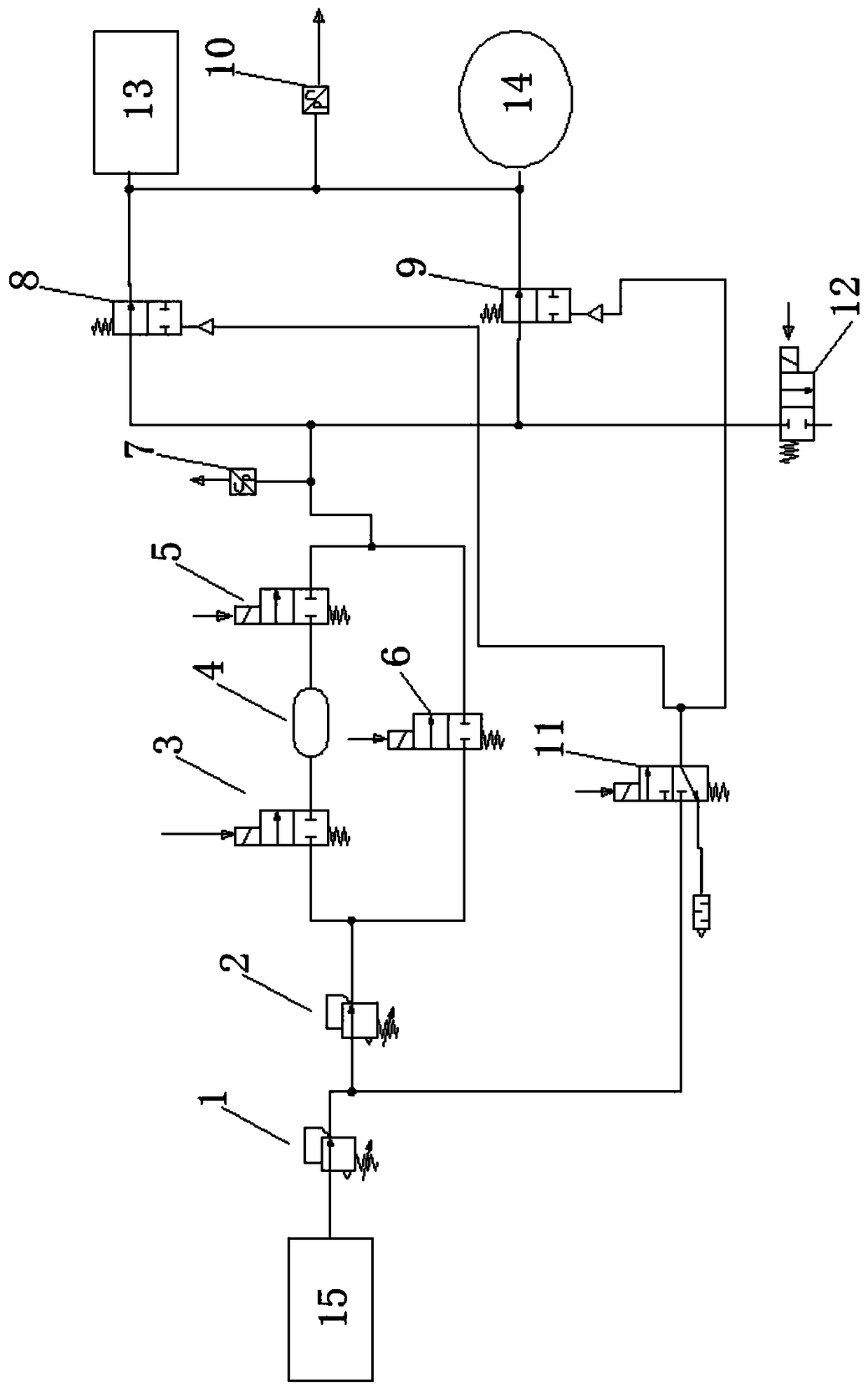
[0050] Since the differential pressure air tightness tester involved in the present invention may be used to detect larger workpieces, these larger test pieces 13 usually need to be fed with a large amount of gas to ensure the accuracy of detection, and only by buffering The speed of the device to inflate the tested part 13 and the standard part 14 is relatively slow, so on the basis of the second embodiment, a bypass solenoid valve 6 is added between the fine pressure regulating valve and the pressure sensor, as shown in the attached image 3 As shown, the bypass solenoid valve 6 is connected in parallel with the air path formed by connecting the first solenoid valve 3, the gas tank 4 and the second solenoid valve 5, and the air inlet of the bypass solenoid valve 6 is connected with the gas outlet of the fine pressure regulating valve 2 , the air outlets of the bypass solenoid valve 6 are respectively connected with the first control valve 8 and the second control valve 9 .

...


PUM


Abstract

The invention relates to a high pressure gas source inflating method and a differential pressure airtightness detector based on the inflating method. The inflating method includes (1) arranging a first valve, a gas tank and a second valve connected in sequence between a high pressure gas source and a work piece; (2) opening the first valve and closing the second valve so as to enable the high pressure gas source to inflate the gas tank; (3) closing the first valve and opening the second valve so as to enable the gas tank to inflate the work piece; (4) opening the first valve and the second valve in an alternating manner so as to enable the pressure of gas of the work piece inflated by the high pressure gas source via the gas tank to reach a preset gas pressure. According to the invention,gas can be inflated into the work piece accurately, so that inflation under micro gas pressure is realized, the application range of the airtightness detector is expanded and the equipment productioncost is reduced substantially.

Description

technical field [0001] The invention relates to the technical field of air tightness testing equipment, in particular to a high-pressure gas source inflation method and a differential pressure air tightness detector based on the inflation method. Background technique [0002] With the progress of society and the development of industrialized production, manufacturers in all walks of life are pursuing high-quality, multi-functional products, while also requiring efficient and clean production processes. Therefore, more and more modern science and technology are applied to production practice. The sealing performance is an important parameter of product performance and quality in the automobile industry, gas appliance industry, semiconductor processing industry, aerospace industry, food industry, medical and health industry and other industries. At present, the most commonly used air tightness testing methods include bubble method, tracer gas detection method, pressure drop d...

Claims


Application Information

Patent Timeline
IPC IPC(8): G01M3/26F17D1/04F17D3/01
CPCG01M3/26F17D1/04F17D3/01
Inventor 冯华王仁辽黄丽萍李宽陈春飞
Owner HANGZHOU GUHENG ENERGY SCI & TECH
Why Eureka
Try Eureka