Infrared thermal imaging detection method for thermal barrier anti-ablation coating defects

A technology of infrared thermal imaging and detection method, which is applied in the direction of material defect testing, etc., can solve the problems that the original thermal image sequence cannot be effectively collected and complete, the quantitative detection and evaluation of coating quality cannot be realized, and the heat transfer cannot be realized, so as to achieve non-destructive The effect of detection, strong operability and high detection efficiency

Active Publication Date: 2018-10-09
安泰天龙钨钼科技有限公司 +1
View PDF8 Cites 0 Cited by
  • Summary
  • Abstract
  • Description
  • Claims
  • Application Information

AI Technical Summary

Problems solved by technology

However, for different complex thermal barrier anti-ablation coating structures, especially multi-layer composite coating structures containing both metal and non-metal materials, traditional light thermal excitation imaging detection cannot effectively transfer heat to each layer of coating, At the same time, when the thermal conductivity characteristics of coating materials are quite different, the original thermal image sequence cannot be effectively collected and complete, and the quantitative detection and evaluation of coating quality cannot be realized.

Method used


Image

  • Infrared thermal imaging detection method for thermal barrier anti-ablation coating defects
  • Infrared thermal imaging detection method for thermal barrier anti-ablation coating defects
  • Infrared thermal imaging detection method for thermal barrier anti-ablation coating defects

Examples


Embodiment Construction

[0025] In order to make the object, technical solution and advantages of the present invention clearer, the implementation manner of the present invention will be further described in detail below in conjunction with the accompanying drawings.

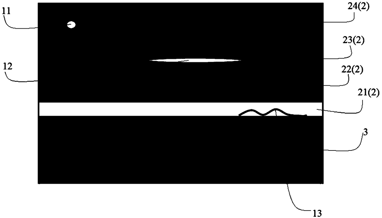
[0026] In application, the thermal barrier anti-ablation coating 2 is disposed on the outer surface of the substrate 3 , and when the structure of the thermal barrier anti-ablation coating 2 is a multilayer structure, each layer is sequentially arranged from the outer surface of the substrate 3 outward. exist figure 1 In the figure, the shown thermal barrier anti-ablation coating 2 is disposed on the upper surface of the substrate 3, including the first layer 21, the second layer 22, the third layer 23 and the fourth layer 24 from bottom to top, a total of 4 layers , that is, the structure of the thermal barrier anti-ablation coating is a 4-layer structure. The material of the matrix 3 may be metal, or non-metallic carbon fiber compos...


PUM


Abstract

The invention discloses an infrared thermal imaging detection method for thermal barrier anti-ablation coating defects, and belongs to the technical field of non-destructive testing. The method comprises the steps of sample preparation, sample detection, parameter determination and test piece detection. Through the technical solution, the infrared thermal imaging detection method can effectively carry out non-contact non-destructive testing on a thermal barrier anti-ablation coating structure and non-destructive testing on the thermal barrier anti-ablation coating defects, particularly solvesthe problem of quantitative detection of coating interface defects in a multilayer composite coating structure, and has the advantages of high operability and high detection efficiency.

Description

technical field [0001] The invention belongs to the technical field of non-destructive testing, and in particular relates to an infrared thermal imaging detection method for defects of a thermal barrier anti-ablation coating. Background technique [0002] Thermal barrier anti-ablation coatings are widely used in ship engines, gas turbines, aircraft fins, empennages, and rudder blades to protect the surface of components that work under harsh conditions such as high temperature and strong airflow. In order to ensure the safety and reliability of components, it is necessary to conduct non-destructive testing and evaluation of the quality status of the thermal barrier anti-ablation coating. [0003] At present, non-destructive testing and evaluation of the quality status of thermal barrier anti-ablation coatings are usually performed based on infrared thermal imaging non-destructive testing methods. In the non-destructive testing methods of infrared thermal imaging, it mainly ...

Claims


Application Information

Patent Timeline
Patent Type & Authority Applications(China)
IPC IPC(8): G01N25/72
CPCG01N25/72
Inventor 黄鑫牛琛辉刘国辉张保红杜仲周武平王铁军
Owner 安泰天龙钨钼科技有限公司
Why Eureka
Try Eureka