Device and method for measuring the angle between the normal line of the light-transmitting surface of an electro-optic crystal and the optical axis of the crystal

A technology of electro-optic crystal and crystal optical axis, which is applied in the direction of geometric characteristics/aberration measurement and optical performance test, which can solve the problems of crystal scratches, difficult analysis of conoscopic interferograms, and difficult construction of measurement devices, etc., to achieve data repeatability Good results

Active Publication Date: 2019-05-17
SHANGHAI INST OF OPTICS & FINE MECHANICS CHINESE ACAD OF SCI
View PDF6 Cites 0 Cited by
  • Summary
  • Abstract
  • Description
  • Claims
  • Application Information

AI Technical Summary

Problems solved by technology

[0004] The invention proposes a device and method for measuring the angle between the normal direction of the light-transmitting surface of the electro-optic crystal and the direction of the optical axis of the crystal, which realizes the non-contact non-destructive detection of the electro-optic crystal, and overcomes the problem that the crystal is prone to scratches and scratches in the existing method. A series of problems such as the difficulty of building the measurement device and the difficulty of analyzing the conoscopic interferogram

Method used


Image

  • Device and method for measuring the angle between the normal line of the light-transmitting surface of an electro-optic crystal and the optical axis of the crystal
  • Device and method for measuring the angle between the normal line of the light-transmitting surface of an electro-optic crystal and the optical axis of the crystal
  • Device and method for measuring the angle between the normal line of the light-transmitting surface of an electro-optic crystal and the optical axis of the crystal

Examples


Embodiment Construction

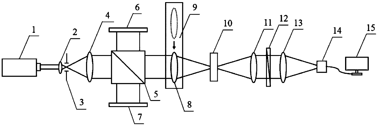
[0034] figure 1 It is a schematic diagram of the angle measuring device between the normal line of the light-passing surface of the electro-optic crystal and the optical axis of the crystal of the present invention. It can be seen from the figure that the measuring device for the angle between the normal line of the light-passing surface of the electro-optic crystal of the present invention and the optical axis of the crystal includes: laser 1, the first First lens 2, pinhole diaphragm 3, second lens 4, beam splitter 5, receiving screen 6, plane mirror 7, third lens 8, one-dimensional precision electric translation stage 9, electro-optic crystal to be tested 10, fourth lens 11, linear polarizing plate 12, the fifth lens 13, image detector 14 and computer 15; Described laser device is linearly polarized light laser 1, and the laser direction that sends out along described linearly polarized light laser 1 is described successively A lens 2, an aperture stop 3, a second lens 4 an...


PUM


Abstract

The present invention provides a device and method for measurement of a light passing surface normal of an electro-optic crystal and an optical axis of an electro-optic crystal. The main components of the device comprise: a linear polarized light laser, a first lens, a small aperture diaphragm, a second lens, a spectroscope, a plane mirror, a receiving screen, a third lens, a one-dimensional precision electric displacement stand, a fourth lens, a linear polaroid, a fifth lens, an image detector and a computer, and a photoelectric autocollimator and a sheet of parallel plate glass with 1'' of depth of parallelism are required for installation and regulation of a light path, etc. The device and method for measurement of the light passing surface normal of the electro-optic crystal and the optical axis of the electro-optic crystal realize non-contact nondestructive detection of the electro-optic crystal to be detected so as to overcome a series of problems that a crystal is easy to generate scratches, a measurement device is difficult to build and a conoscopic interference pattern is difficult to analyze in the current method. The third lens and the fourth lens change different F numbers to perform measurement of electro-optic crystals with different thicknesses. The data repeatability of measurement is good, and compared to the measurement data of a current X-ray crystal direction finder, the relative error is within 30''.

Description

technical field [0001] The invention relates to the field of optical measurement and detection, in particular to a device and method for measuring the angle between the normal direction of the light-transmitting surface of an electro-optic crystal and the direction of the crystal optical axis. Background technique [0002] Electro-optic crystals are often used in optical modulators and optical switching devices. Because they are usually cut along the direction perpendicular to their optical axis during processing, the determination of their optical axis direction is particularly important. The axis-fixing error determines the cutting error. With the increase of the cutting error, the optical energy loss will increase rapidly during the use of the electro-optic crystal, and the conversion efficiency will also decrease accordingly. Therefore, it is necessary to measure the optical axis direction of the electro-optic crystal very accurately. The general method seen on the mark...

Claims


Application Information

Patent Timeline
Patent Type & Authority Patents(China)
IPC IPC(8): G01M11/02
CPCG01M11/0242
Inventor 刘世杰鲁棋周游王圣浩徐天柱王微微邵建达
Owner SHANGHAI INST OF OPTICS & FINE MECHANICS CHINESE ACAD OF SCI
Why Eureka
Try Eureka