Perimeter stereoscopic protection system

A protection system and three-dimensional technology, applied in anti-theft alarms, anti-theft alarm mechanical start-ups, instruments, etc., can solve problems such as being easily affected, poor stability, false alarms, etc., to achieve a wide range of applications, increase stability, and increase reliability Effect

Inactive Publication Date: 2018-10-09
河南海象信息技术有限公司
View PDF5 Cites 1 Cited by
  • Summary
  • Abstract
  • Description
  • Claims
  • Application Information

AI Technical Summary

Problems solved by technology

[0005] The purpose of the present invention is to provide a three-dimensional perimeter protection system, which solves the problem of low reliability and poor stability of the existing perimeter protection system, which is easily affected and leads to false alarms, thus affecting the work efficiency of security personnel

Method used


Image

  • Perimeter stereoscopic protection system

Examples


Embodiment 1

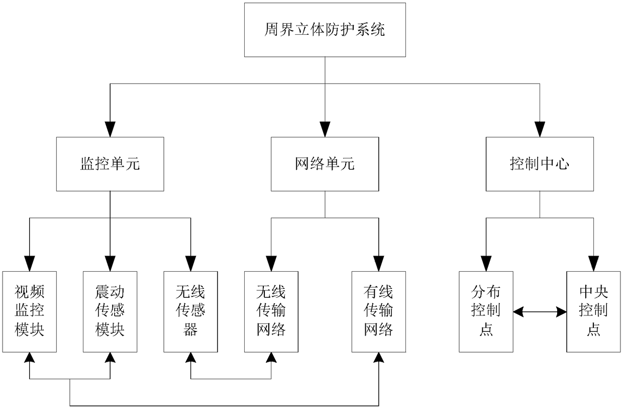
[0039] A perimeter three-dimensional protection system provided by a preferred embodiment of the present invention includes a monitoring unit, a network unit and a control center, the monitoring unit is connected to the network unit, and the network unit is connected to the control center;

[0040] The monitoring unit is used for target identification, judgment and warning, and collects information for intelligent identification, and locates the warning position, and finally transmits monitoring information to the control center through the network unit;

[0041] The network unit transmits information through a wired network, and then assists the wired network through a wireless network to perform supplementary monitoring of blind spots;

[0042] The control center is used for receiving monitoring information, summarizing and processing system information, and issuing instructions.

[0043] Further, the monitoring unit includes a video monitoring module, a vibration sensing modu...

Embodiment 2

[0049] On the basis of Embodiment 1, further, the monitoring unit is also connected with an access control system and an audible and visual alarm system. Realize the integration of existing security technology and new security system, adopt a variety of monitoring methods and modes, reasonably arrange monitoring points and monitoring surfaces, and achieve monitoring without blind spots and security without loopholes with optimal configuration.

Embodiment 3

[0051] On the basis of Embodiment 2, further, the network unit includes a wired transmission network and a wireless transmission network, and the wired transmission network is respectively connected to the video monitoring module and the shock sensor module for information transmission; the wireless transmission network Wireless connection with wireless sensors, auxiliary wired transmission network, and supplementary monitoring of blind spots.

[0052] This embodiment uses two methods for information transmission. Even if one of the networks fails, the other can transmit the monitoring information to the control center and connect to each module of the monitoring unit respectively, ensuring the timeliness of information transmission and preventing a certain The situation where the entire system cannot be used due to network freeze or failure occurs.


PUM


Abstract

The invention discloses a perimeter stereoscopic protection system belonging to the technical field of safety protection systems. The system includes a monitoring unit, a network unit and a control center. The monitoring unit is connected with the network unit. The network unit is connected with the control center. The monitoring unit includes a video monitoring module, a vibration sensing moduleand a wireless sensor, each of two being connected to each other. The network unit includes a wired transmission network and a wireless transmission network. The wired transmission network is connected with the video monitoring module and the vibration sensing module. The wireless transmission network is connected with the wireless sensor in a wireless manner. The control center includes distributive control points and a central control point that are in information communication. The invention solves a problem that a prior perimeter protection system is low in reliability, poor in stability,susceptible to influence and thus sends error report that affecting working efficiency of security guards.

Description

technical field [0001] The invention belongs to the technical field of security systems, and relates to a perimeter three-dimensional protection system. Background technique [0002] In recent years, with the changes in the socio-economic structure, urban construction has become more and more modernized, and with the increasing population flow, it has also brought some unstable factors. In the investigation of various crimes, it is found that theft is the most rampant, and among them, burglary accounts for a high proportion. Some high-end residential areas, production plants, office areas, schools and other closed places with sound facilities and valuable items have become the primary targets of coveted and patronized by thieves. Although these places are equipped with security teams, human defense is incomplete after all, and there are inevitably blind spots in prevention. A slight negligence can easily be exploited by thieves, resulting in damage to property and even pers...

Claims


Application Information

Patent Timeline
Patent Type & Authority Applications(China)
IPC IPC(8): G08B25/00G08B25/10G08B13/02G08B13/196
CPCG08B13/02G08B13/196G08B25/00G08B25/10
Inventor 胡茂骏
Owner 河南海象信息技术有限公司
Why Eureka
Try Eureka