Eureka AIR delivers breakthrough ideas for toughest innovation challenges, trusted by R&D personnel around the world.

Ladle for spheroidizing and manufacturing process thereof

A technology of spheroidization treatment and manufacturing process, which is applied in the direction of manufacturing tools, metal processing equipment, casting molten material containers, etc., can solve the problems affecting cost and spheroidization quality, high production cost, high process requirements, etc., and achieve excellent spheroidization effect , The effect of low manufacturing difficulty and low height

Active Publication Date: 2018-10-12
GUANGDONG ZHONGTIAN CHUANGZHAN DUCTILE IRON CO LTD
View PDF21 Cites 0 Cited by
  • Summary
  • Abstract
  • Description
  • Claims
  • Application Information

AI Technical Summary

Problems solved by technology

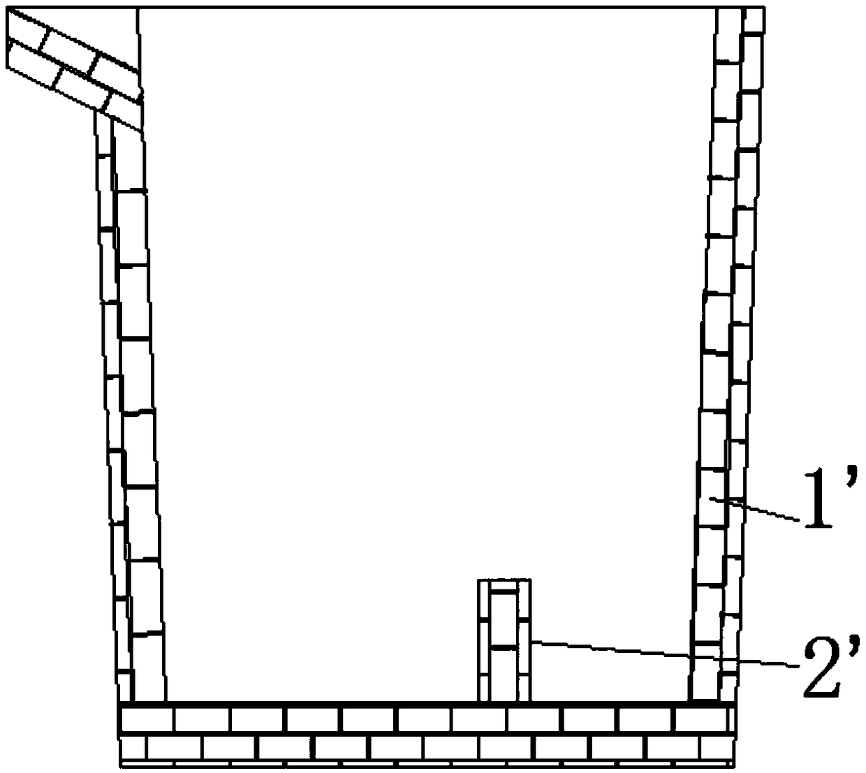
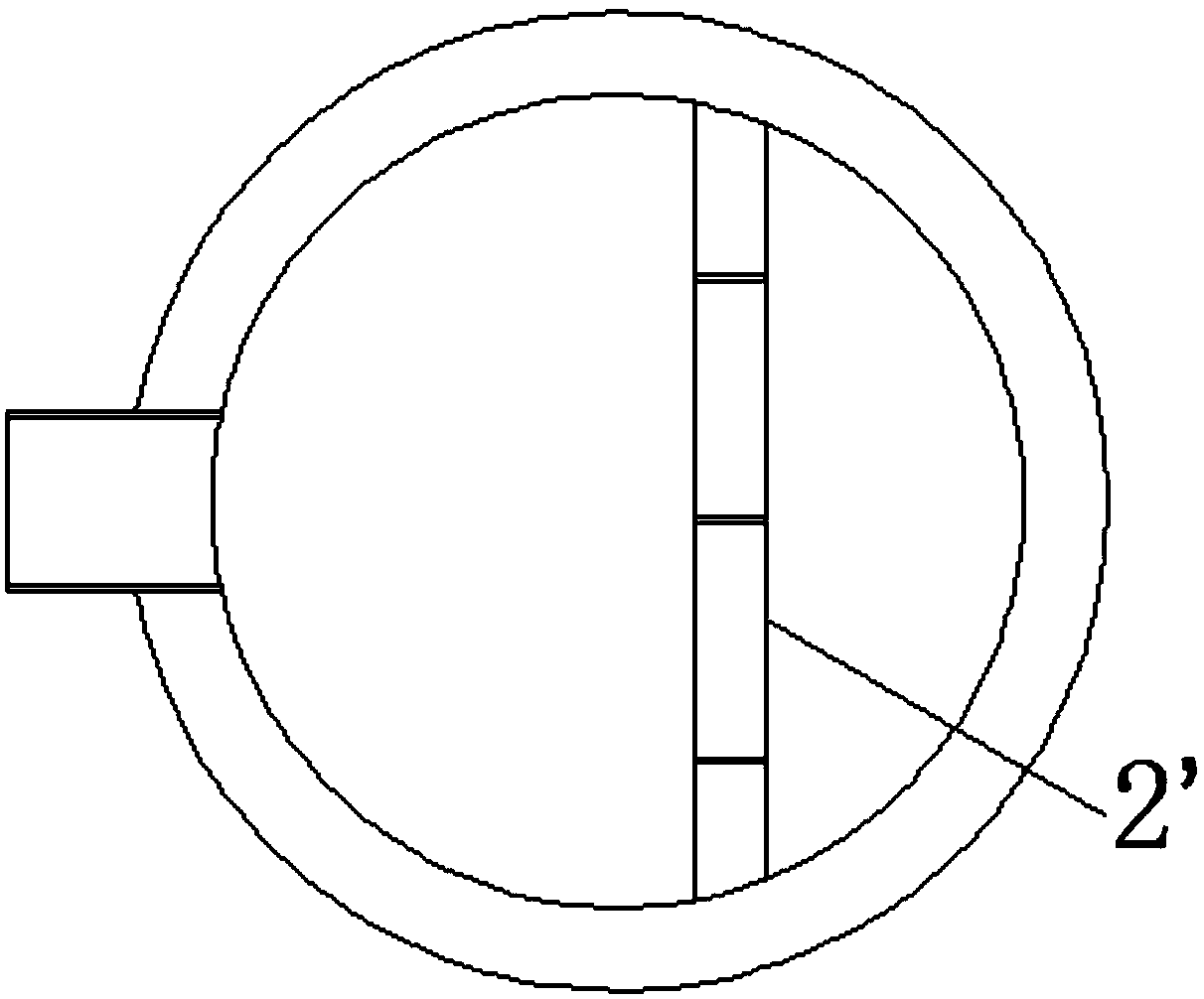
Due to the limited strength of the refractory brick dam 2', coupled with the erosion and erosion of molten iron, the refractory brick dam 2' will collapse soon and need to be rebuilt. In the past, the cost and spheroidizing quality will inevitably be affected
[0004] (2) A traditional type of ladle is poured and formed with castables as a whole. Because the castables are expensive, the overall production cost is relatively high, and because the side walls of the ladle are high, the pouring process requires high requirements and is difficult to manufacture. At the same time, it requires Use special equipment to sinter the lining material

Method used


Image

  • Ladle for spheroidizing and manufacturing process thereof
  • Ladle for spheroidizing and manufacturing process thereof
  • Ladle for spheroidizing and manufacturing process thereof

Examples


Embodiment 1

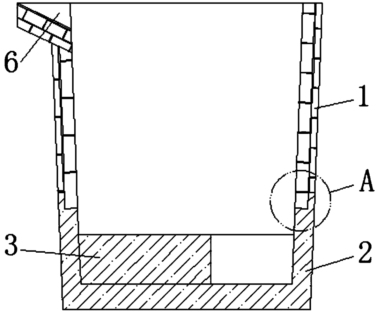
[0048] refer to Figure 3-5 As shown, a ladle for spheroidizing treatment of the present invention includes an upper side wall 1 built with refractory bricks and a spheroidizing chamber 2 cast with castables, the lower part of the upper side wall 1 and the side of the spheroidizing chamber 2 The upper part of the wall is sealed and connected, and the spheroidizing chamber 2 includes a dam 3 located on the inside of the bottom, and the inside of the spheroidizing chamber 2 is divided into a buffer pit 4 and a nodulizing agent placement pit 5 .

[0049] A ladle for spheroidization treatment according to the present invention, its upper side wall 1 is built with traditional refractory bricks, and the spheroidization chamber 2 formed by pouring castables, the inner side of the bottom of the spheroidization chamber 2 is a dam 3 , the embankment 3 divides the inside of the spheroidizing chamber 2 into a buffer pit 4 and a nodulizer placement pit 5. During pouring operations, molten ...

Embodiment 2

[0073] Such as Figure 6 As shown, the ladle for spheroidizing treatment in Example 2 of the present invention is basically the same as that in Example 1, and it includes all the features of the ladle for spheroidizing treatment in Example 1. In addition, the middle part of the embankment 3 and the part of the embankment 3 located on one side of the buffer pit 4 are higher than the rest. When treating molten iron by spheroidization, because the part of the embankment 3 located on one side of the buffer pit 4 is higher, the molten iron will flow from the other side of the buffer pit 4 to the nodulizer placement pit 5, and the middle part of the embankment 3 is also higher, and the molten iron will Sequentially flow through a plurality of nodulizer placement pits 5 for effective nodularization. Before the molten iron enters the molten iron ladle for nodulizing treatment, the nodulizing agent is put into a plurality of nodulizing agent placement pits 5 along the molten iron flow...


PUM

PropertyMeasurementUnit
thicknessaaaaaaaaaa
heightaaaaaaaaaa
thicknessaaaaaaaaaa

Abstract

The invention belongs to the field of ladles, and relates to a ladle for spheroidizing. The ladle for spheroidizing comprises an upper side wall constructed by refractory bricks, and a spheroidizing chamber moulded by casting castable, wherein the lower part of the upper side wall and the upper part of a side wall of the spheroidizing chamber are connected in a sealing way; and the spheroidizing chamber comprises a dam located on the inner side of the bottom part of the spheroidizing chamber and used for dividing the inner part of the spheroidizing chamber into a cushion pit and a spheroidizing agent placement pit. A manufacturing process of the ladle for spheroidizing provided by the invention comprises the steps of (1) preparing raw materials of the castable of the spheroidizing chamber;(2) starting casting for the spheroidizing chamber; (3) baking and sintering the spheroidizing chamber; (4) manufacturing a packing of the upper side wall; (5) baking; and (6) heating the ladle through high-temperature molten iron for 2 to 3 times. The ladle for spheroidizing and the manufacturing process provided by the invention have the characteristics of long service life of the ladle, low cost, low difficulty in manufacturing, and an excellent ladle spheroidizing effect.

Description

technical field [0001] The invention relates to a molten iron ladle, more specifically, to a molten iron ladle for spheroidizing treatment and a manufacturing process thereof. Background technique [0002] The molten iron ladle is used for the pouring operation in the iron and steel foundry workshop. After accepting the molten iron in front of the furnace, it is transported to the casting mold by driving for pouring. When pouring, the deceleration mechanism installed on the bag body is driven manually or electrically to make the bag body tilt, and the casting mold is poured. The spheroidizing ladle is different from the gray iron ladle. Generally, a dam is set at the bottom of the ladle. During spheroidizing treatment, the spheroidizing agent is placed on the other side of the water outlet, which is also close to the pouring side, so as to avoid the impact of the molten iron on the spheroidizing. Agent hedging, play the effect of delaying the nodularization. However, the m...

Claims


Application Information

Patent Timeline
Patent Type & Authority Applications(China)
IPC IPC(8): B22D41/00C21C7/00C04B35/66
CPCC21C7/00C04B35/66B22D41/00C04B2235/3418C04B2235/3272C04B2235/3241C04B2235/3232C04B2235/3217Y02P10/20
Inventor 柯志敏陈鹏辉陈永成
Owner GUANGDONG ZHONGTIAN CHUANGZHAN DUCTILE IRON CO LTD
Why Eureka
Eureka Blog
Learn More