Mechanical grabbing hand for scaffold

A scaffolding and grasping hand technology, applied in the direction of manipulators, chucks, manufacturing tools, etc., can solve the problems of personnel damage to parts, unable to maintain, loss, etc., to reduce losses, prevent damage or personnel damage, and maintain firm clamping sexual effect

Pending Publication Date: 2018-10-12
WUXI SAFETY SCAFFOLDING
View PDF1 Cites 3 Cited by
  • Summary
  • Abstract
  • Description
  • Claims
  • Application Information

AI Technical Summary

Problems solved by technology

[0007] Although this kind of pneumatic manipulator is simple in structure, low in production cost, easy to use, reliable, flexible in action, reduces labor intensity and improves production efficiency, but because its jaws are driven by cylinders, using this kind of pneumatic manipulator to clamp more expensive or For heavy parts, once there is a problem with the cylinder or a power failure, the claws cannot maintain the clamping state, and the clamped parts will fall, which will easily cause personal injury and parts damage, and suffer greater losses

Method used


Image

  • Mechanical grabbing hand for scaffold
  • Mechanical grabbing hand for scaffold
  • Mechanical grabbing hand for scaffold

Examples


Embodiment 1

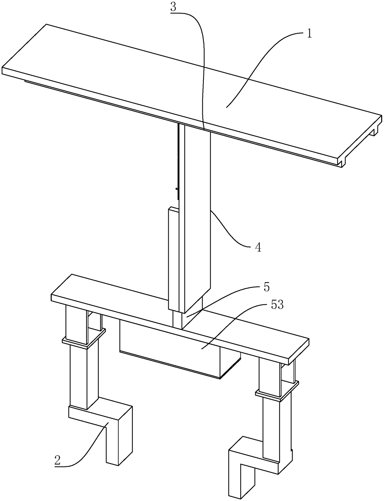
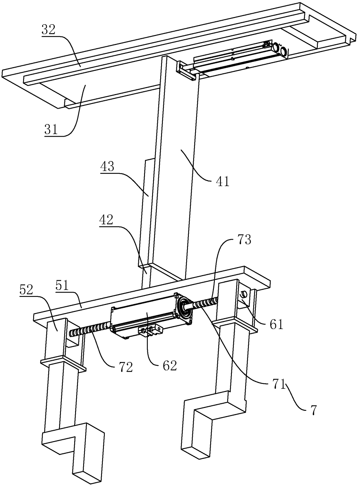
[0037] Embodiment 1, a kind of mechanical grasping hand for scaffolding, such as figure 1 and figure 2 As shown, it includes the mounting plate 1 and the jaw 2. The X-axis action mechanism 3, the Y-axis action mechanism 4, and the Z-axis action mechanism 5 are connected in sequence between the installation plate 1 and the jaw 2. The X-axis action mechanism 3 slides Connected to the mounting plate 1, it can drive the jaws 2 to move in the X-axis direction; the Y-axis action mechanism 4 is slidably connected to the X-axis action mechanism 3, and can drive the jaws 2 to move in the Y-axis direction; the Z-axis action mechanism 5. It is slidingly connected to the Y-axis action mechanism 4, and is used to drive the jaw 2 to move in the Z-axis direction.

[0038] Such as figure 1 and figure 2 As shown, the Z-axis action mechanism 5 is also provided with a driving mechanism 6, which is connected with the jaws 2 and is used to drive the jaws 2 to complete the clamping of parts. ...

Embodiment 2

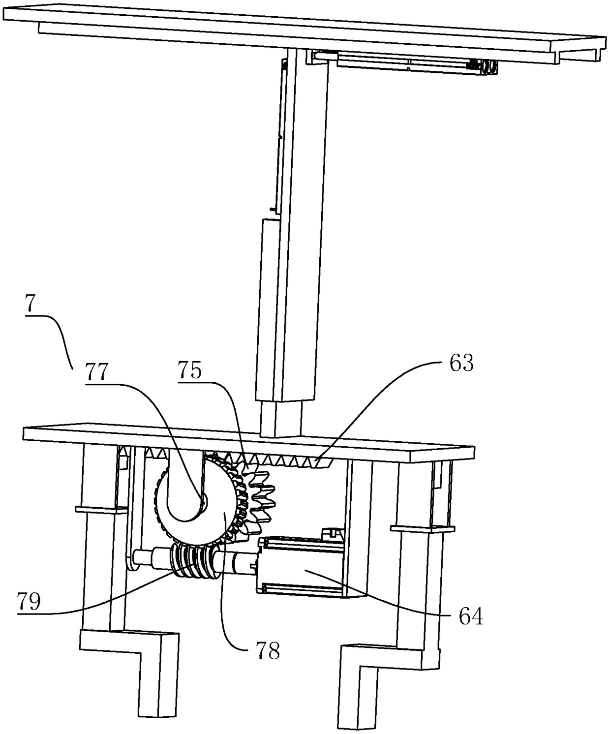
[0043] Embodiment 2, a kind of mechanical grasping hand for scaffolding, such as image 3 As shown, the difference from Embodiment 1 is that the drive mechanism 6 includes two movable racks 63 that are oppositely arranged and slidably connected to the Z-axis action mechanism 5, and the corresponding movable racks 63 are provided on the Z-axis action mechanism 5. The driving gear 75, the movable rack 63 is driven to rotate by the driving gear 75.

[0044] The driving gear 75 is connected to the Z-axis action mechanism 5 through the rotation shaft 77, and the locking mechanism 7 includes a drive worm gear 78 fixed on the rotation shaft 77 and a drive worm gear 78 that is rotatably connected to the Z-axis action mechanism and meshed with the drive worm gear 78. The driving worm 79, the driving mechanism 6 also includes a driving motor 64 for driving the driving worm 79 to rotate.

[0045] The driving motor 64 drives the driving worm 79 to rotate, thereby driving the worm gear 78...


PUM


Abstract

The invention discloses a mechanical grabbing hand for a scaffold, and aims at providing the mechanical grabbing hand for the scaffold, wherein the mechanical grabbing hand has the beneficial effectsthat when the emergency situation of power failure or damage happens, clamping is still firm, and subsequent personnel hurt and object damage are not likely to happen. According to the technical scheme, the mechanical grabbing hand comprises an installing plate and a clamping jaw, an X-axis action mechanism, a Y-axis action mechanism, a Z-axis action mechanism, a drive mechanism and a locking mechanism are sequentially connected between the installing plate and the clamping jaw, the locking mechanism is connected with the drive mechanism and used for driving and locking the drive mechanism, and the situation that the drive mechanism reversely rotates, and a clamped object falls down is prevented. The locking mechanism can lock the position of the clamping jaw, even when the situation of the power failure or drive mechanism faults is encountered, the firmness of clamping of the object through the clamping jaw can be kept, the situation that the object falls off from the clamping jaw, and consequently object damage or personnel hurt is caused is prevented, and the losses caused when the emergency situation happens are reduced.

Description

technical field [0001] The invention relates to the field of manipulator equipment, in particular to a mechanical grabbing hand for scaffolding. Background technique [0002] The manipulator can imitate certain motion functions of the human hand and arm, and is used to grab, carry objects or operate automatic operating devices according to a fixed program. The manipulator is the earliest industrial robot and the first modern robot. It can replace the heavy labor of people to realize the mechanization and automation of production, and can operate in harmful environments to protect personal safety. Therefore, it is widely used in machinery manufacturing, metallurgy, Departments of electronics, light industry and atomic energy. [0003] The manipulator is mainly composed of three parts: the actuator, the drive mechanism and the control system. The hand is a part used to grasp the workpiece (or tool), and there are various structural forms according to the shape, size, weight,...

Claims


Application Information

Patent Timeline
Patent Type & Authority Applications(China)
IPC IPC(8): B25J15/08B25J15/02B25J5/02
CPCB25J15/083B25J5/02B25J15/02
Inventor 黄国庆
Owner WUXI SAFETY SCAFFOLDING
Why Eureka
Try Eureka