Rapid detection equipment for ECU of electric vehicle

A technology for testing equipment and electric vehicles, applied in electrical testing/monitoring, testing/monitoring control systems, instruments, etc., can solve problems such as affecting testing efficiency, unfavorable rapid testing for enterprises, slow testing speed, etc. The effect of high detection and device detection speed

Active Publication Date: 2020-05-08
斯比泰电子(嘉兴)有限公司
View PDF6 Cites 2 Cited by
  • Summary
  • Abstract
  • Description
  • Claims
  • Application Information

AI Technical Summary

Problems solved by technology

For this reason, an object of the present invention is to provide a kind of electric vehicle ECU rapid detection equipment, can solve the existing performance detection and rotate and need workers to carry out loading and unloading, make detection speed slow, be unfavorable for the enterprise to carry out fast detection, at the same time when rejecting defective products, need Shutdown for elimination also affects the overall detection efficiency

Method used


Image

  • Rapid detection equipment for ECU of electric vehicle
  • Rapid detection equipment for ECU of electric vehicle
  • Rapid detection equipment for ECU of electric vehicle

Examples


Embodiment 1

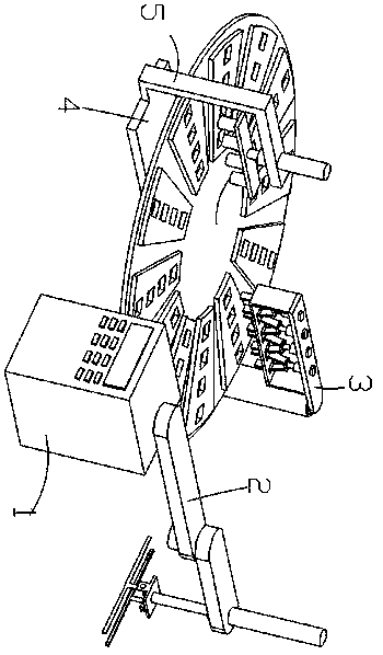
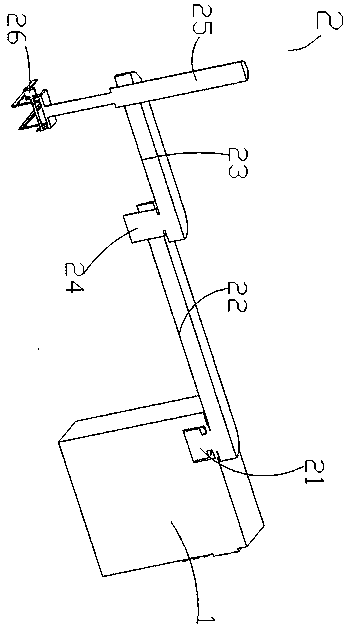
[0031] Such as figure 1 , 2As shown in and 4, a fast detection device for an electric vehicle ECU includes a control structure 1, a loading and unloading structure 2, a defective product rejecting structure 3, a rotating structure 4, and a detection structure 5. The top of the control structure 1 is provided with a loading and unloading structure 2, and the upper and lower The material structure 2 comprises a first rotating motor 21, a first rotating plate 22, a second rotating plate 23, a second rotating motor 24, a first electric push rod 25 and a long plate-shaped clamping structure 26, and the first rotating motor 21 is connected with The first rotating plate 22, the control structure 1 includes a control box and a control panel, the first rotating motor 21 is fixedly connected in the through hole at the top of the control box of the control structure 1, and the through hole at the top of the control box of the control structure 1 passes through the fixedly connected beari...

Embodiment 2

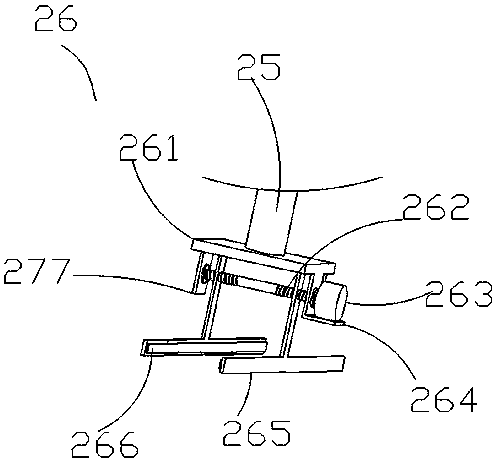
[0033] Such as image 3 As shown, the foundation of Embodiment 1 has been increased, and the long plate-shaped clamping structure 26 includes a horizontal plate 261, a threaded rod 262, a motor 263, a motor mounting plate 264, a T-shaped sliding clamping plate 265 and a straight plate 207, and the horizontal plate 261 and the first The telescopic rod of the electric push rod 25 is fixedly connected, and the bottom of the horizontal plate 261 is symmetrically fixedly connected with a straight plate 207, and the straight plate 207 is rotatably connected with a threaded rod 262 provided with threaded symmetry through a fixedly connected bearing, and the threaded rod 262 is connected with a T-shaped symmetrical thread. The sliding splint 265 and the inner wall of the T-shaped sliding splint 265 are fixedly connected with a rubber plate 266. By designing the rubber plate 266 on the T-shaped sliding splint 265, the rubber plate 266 increases the friction to ensure the clamping stabil...

Embodiment 3

[0035] Such as figure 1 , 4 , 5 and 6, the basis of embodiment 1 has been increased, and the rotating structure 4 includes a base plate 41, a straight cylinder 42 is fixedly connected to the middle end of the top of the base plate 41, and a fourth rotating motor 43 is fixedly connected to the bottom of the straight cylinder 42, and the fourth rotating motor The output end of 43 is fixedly connected with a turntable 44, the bottom of the turntable 44 is fixedly connected with the bearing fixedly connected with the top of the straight tube 42, and the turntable 44 is uniformly fixedly connected with a fan-shaped plate 46 along the circumferential direction, and the fan-shaped plate 46 is evenly provided with placement holes 45 , the depth of the placement hole 45 is 3-5mm; the front and rear sections of the bottom plate 41 are respectively provided with a defective product rejection structure 3 and a detection structure 5, and the detection structure 5 includes an L-shaped plate...


PUM


Abstract

The invention relates to the technical field of electric vehicles. The invention relates to rapid detection equipment for an ECU of an electric vehicle. The equipment comprises a control structure, the control structure is provided with a feeding and discharging structure, the feeding and discharging structure comprises a first rotating motor, the first rotating motor is provided with a first rotating plate, the first rotating plate is provided with a second rotating motor, the second rotating motor is provided with a second rotating plate, the second rotating plate is provided with a first electric push rod, and the first electric push rod is provided with a long-plate-shaped clamping structure; the rotating structure comprises a bottom plate, the bottom plate is provided with a straightcylinder, the straight cylinder is provided with a fourth rotating motor, the fourth rotating motor is provided with a turntable, and the turntable is provided with a fan-shaped plate which is provided with placing holes; the bottom plate is provided with an inferior-quality product removing structure and a detection structure, the detection structure comprises an L-shaped plate, and the L-shapedplate is provided with a second electric push rod which is provided with a detection head mounting plate; the device is high in detection speed and beneficial to rapid detection of enterprises.

Description

technical field [0001] The invention relates to the technical field of electric vehicles, in particular to a fast detection device for an electric vehicle ECU. Background technique [0002] Electric vehicles refer to vehicles that use electric energy as a power source and are driven by electric motors. They are new energy vehicles, including pure electric vehicles (BEV), hybrid electric vehicles (HEV) and fuel cell electric vehicles (FCEV). Because its impact on the environment is relatively small compared with traditional cars, its development prospects are widely optimistic, but the technology is still immature. [0003] ECU (Electronic Control Unit) electronic control unit, also known as "driving computer", "vehicle computer" and so on. In terms of use, it is a special microcomputer controller for automobiles. It is the same as an ordinary computer. It consists of a microprocessor (MCU), a memory (ROM, RAM), an input / output interface (I / O), an analog-to-digital converter...

Claims


Application Information

Patent Timeline
Patent Type & Authority Applications(China)
IPC IPC(8): G05B23/02
CPCG05B23/0221
Inventor 石强万峰高月培袁卫平李春洋邓秋林金长根
Owner 斯比泰电子(嘉兴)有限公司
Why Eureka
Try Eureka