Method of cutting and correcting workpiece by applying laser

A laser cutting and workpiece technology, applied in laser welding equipment, manufacturing tools, metal processing equipment, etc., can solve the problems of limited operator's subjective judgment, large processing errors, etc., to ensure accurate movement, reduce processing errors, and ensure clamping The effect of maintaining stability

CN110039201AInactive Publication Date: 2019-07-23HANGZHOU MULIN EYEWEAR CO LTD
5 Cites 2 Cited by

Patent Information

Authority / Receiving Office
CN · China
Patent Type
Applications(China)
Current Assignee / Owner
Publication Date
2019-07-23
Estimated Expiration
Not applicable · inactive patent

Smart Images

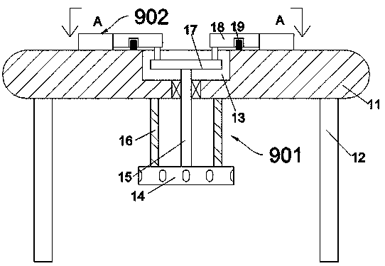
  • Figure 1
    Figure 1
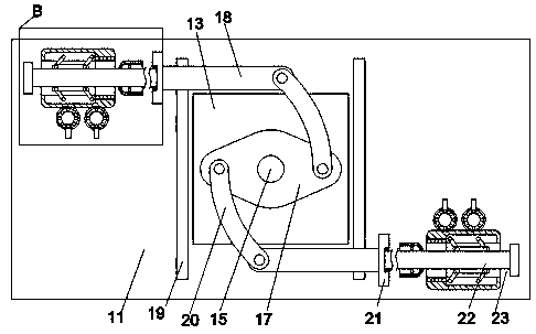
  • Figure 2
    Figure 2
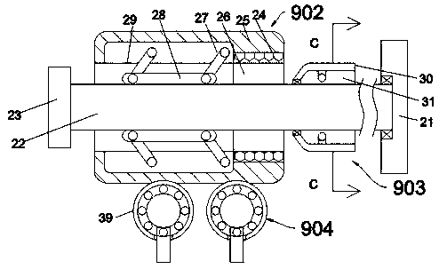
  • Figure 3
    Figure 3
Patent Text Reader

Abstract

The invention discloses a method of cutting and correcting a workpiece by applying laser. A collecting device comprises a correcting platform, wherein a rotating cavity with an upward opening is formed in the correcting platform; and the inner wall of the bottom end of the rotating cavity is rotatably connected to a front correcting device and a rear correcting device. The integrity of the heightis guaranteed through the correcting structure arranged on the same height plane; the adoption of a fixed clamping structure similar to a spherical bearing ensures the clamping stability, and also facilitates the disassembly and assembly work; the structures with different movement capabilities, which are brought about by using the positive and negative rotation on the same shaft, optimize the operation steps, and also ensure the precise movement of the workpiece in the left and right direction; the adoption of the structure of stirring turning wheels with feet can realize the adjustment of the workpiece in the front and rear direction; the whole equipment can be operated by one person, avoids the need for the multi-person collaboration during laser processing, and reduces machining errorscaused by subjective judgment factors of multiple groups of operators.
Need to check novelty before this filing date? Find Prior Art

Description

technical field

[0001] The invention relates to the technical field of laser cutting and calibration, in particular to a method for applying laser cutting and correcting workpieces. Background technique

[0002] Laser cutting is to irradiate the workpiece with a focused high-power-density laser beam, so that the workpiece material at the irradiated place is melted, gasified, ablated or reached the ignition point, and at the same time, the molten material is blown away by the high-speed airflow coaxial with the laser beam, thereby A thermal cutting method that realizes cutting the workpiece. Due to its fast cutting speed, laser cutting requires strict proofreading of the cutting position of the workpiece before cutting. The traditional method is to use a structure similar to a lathe to achieve adjustment in three directions. This process requires the participation of multiple personnel, and the operation The more the number, the stronger the interference of subjective judgme...

Examples

Embodiment Construction

[0022] Combine below Figure 1-7 The present invention is described in detail, and for convenience of description, the orientations mentioned below are now stipulated as follows: figure 1 The up, down, left, right, front and back directions of the projection relationship itself are the same.

[0023] The present invention relates to a method for applying laser cutting and correcting workpieces, which is mainly used in the process of correcting workpieces by laser cutting chambers. The present invention will be further described below in conjunction with the accompanying drawings of the present invention:

[0024] According to a method of applying laser cutting and correcting a workpiece according to the present invention, the proofreading device includes a proofreading platform 11, and the proofreading platform 11 is provided with a rotating chamber 13 with an upward opening, and the inner wall of the bottom end of the rotating chamber 13 is rotatably connected with a Front a...