
Pouring tool for a nodular cast iron jacking pipe and working method thereof

A technology for ductile iron and pipes, applied in the field of pouring tooling, can solve the problems of easy to run slurry, no special sealing treatment on the socket, affecting product consistency, etc.

Active Publication Date: 2018-10-12
XINXING DUCTILE IRON PIPES CO LTD
View PDF8 Cites 4 Cited by
  • Summary
  • Abstract
  • Description
  • Claims
  • Application Information

AI Technical Summary

Problems solved by technology

[0003] Chinese invention patent CN201610521066.4 "A kind of propulsion tube outer wall grouting equipment and its use method" and Chinese invention patent CN201610978969.5 "Ductile iron cast pipe outsourcing cement mortar steel mold" both provide a tool for making ductile iron pipe jacking, The pouring positions are all located at the lower part of the push flange, which cannot take into account the ductile iron pipe jacking (the push flange has long slot holes and hoisting hole) production
[0004] At the same time, in the first two patents, the ductile iron pipe and the base cannot be positioned accurately, and the socket is not specially sealed, which is easy to cause defects due to slippage, affects product consistency, and increases the workload of repairs.
There is no rounding device on the top of the grouting form, which may easily cause the top of the concrete to be elliptical
In addition, it does not consider the production methods of products of different lengths

Method used


Image

  • Pouring tool for a nodular cast iron jacking pipe and working method thereof
  • Pouring tool for a nodular cast iron jacking pipe and working method thereof
  • Pouring tool for a nodular cast iron jacking pipe and working method thereof

Examples


Embodiment Construction

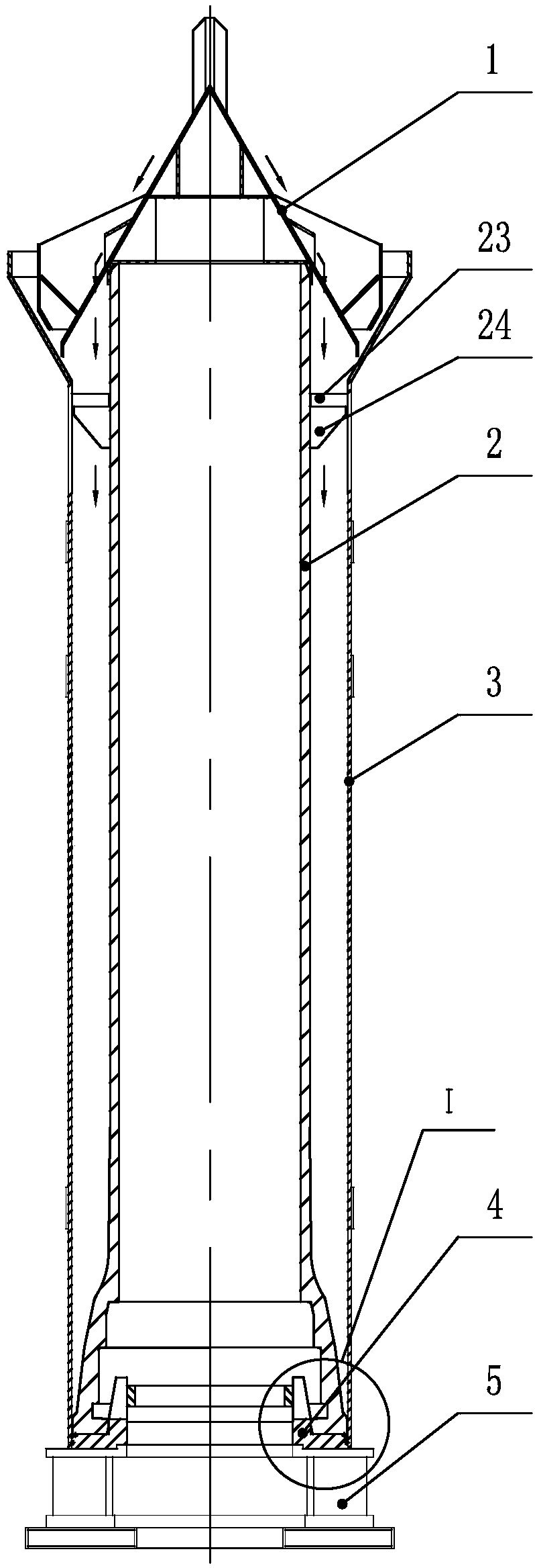
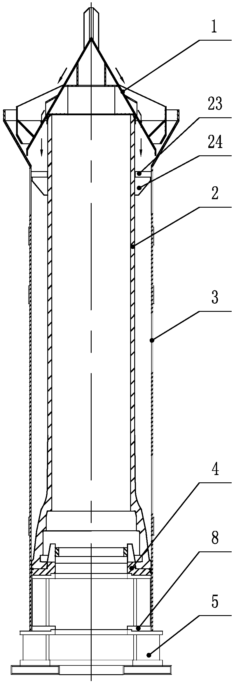
[0032] Such as figure 1 , 5 , 7, and 8, a casting tooling for ductile iron pipe jacking, comprising a perforated blanking cone 1, a flexible outer mold 3, a movable bottom mold 4 and a fixed bottom mold 5 placed sequentially from top to bottom; the fixed bottom mold 5 The lower part is fixed to the ground, the upper part is fixedly connected with the movable bottom mold 4, and a flexible outer mold 3 is installed on the outer side of the upper part; The ductile iron pipe jacking 2 is composed of a ductile iron pipe jacking socket 21, a ductile iron pipe jacking socket 22, a pushing flange 23, a flange rib plate 24 and a pipe body.

[0033]The upper part of the movable bottom mold 4 is provided with a guide slope 42, a support ring 41, a positioning cylinder 43, an end face seal groove 44 and a ring seal groove 45, and the support ring 41 is located on the inner side of the guide slope 42. Below the guide slope 42 is a positioning cylindrical surface 43, and the edge of the o...


PUM

PropertyMeasurementUnit
heightaaaaaaaaaa

Abstract

The invention discloses a pouring tool for a nodular cast iron jacking pipe and a working method thereof. The pouring tool comprises a trepanning blanking cone, a flexible external die, a movable bottom die and a fixed bottom die sequentially arranged from top to bottom, wherein the lower part of the fixed bottom die is fixed with the ground; the upper part of the fixed bottom die is fixedly connected with the movable bottom die; the flexible external die is mounted on the outer side of the upper part of the fixed bottom die; the lower part of the movable bottom die is fixedly connected with the fixed bottom die; and the nodular cast iron jacking pipe is mounted at the upper part of the movable bottom die and is composed of a nodular cast iron jacking pipe inserting opening, a nodular castiron jacking pipe bellmouth, a pushing flange, a flange rib plate and a pipe body. The pouring tool is convenient to assemble and facilitates reduction of labor intensity; through overlapped matchingof support rings, manufacture of outer wrapped concrete of the nodular cast iron jacking pipes with different lengths is realized and pouring of the flange with a long slotted hole or without a longslotted hole can be realized.

Description

technical field [0001] The invention relates to the technical field of pouring tooling for making pipes wrapped with concrete, in particular to a pouring tooling suitable for making ductile iron pipe jacking. Background technique [0002] The ductile iron pipe jacking is made by welding the jacking flange on the socket of the ordinary ductile iron pipe and outsourcing the concrete. It is suitable for the construction of pipe jacking (a laying technology without pipe trench). [0003] Chinese invention patent CN201610521066.4 "A kind of propulsion tube outer wall grouting equipment and its use method" and Chinese invention patent CN201610978969.5 "Ductile iron cast pipe outsourcing cement mortar steel mold" both provide a tool for making ductile iron pipe jacking, The pouring positions are all located at the lower part of the push flange, which cannot take into account the ductile iron pipe jacking (the push flange has long slot holes and hoisting hole) production. [0004]...

Claims


Application Information

Patent Timeline
Patent Type & Authority Applications(China)
IPC IPC(8): B28B19/00
CPCB28B19/0038
Inventor 谷兴海李军武月梅左超
Owner XINXING DUCTILE IRON PIPES CO LTD
Learn More