Partitioned continuous tunnel kiln carbonization furnace

A tunnel kiln and sub-regional technology, used in coke ovens, special forms of dry distillation, petroleum industry, etc., can solve the problems of uneven carbonization, low production efficiency, slow heat transfer, etc., and achieve efficient treatment, energy saving, and improved production efficiency. Effect

Pending Publication Date: 2018-10-12
陈学锋
View PDF2 Cites 2 Cited by
  • Summary
  • Abstract
  • Description
  • Claims
  • Application Information

AI Technical Summary

Problems solved by technology

[0004] In the carbonization process of the traditional carbonization furnace, the three stages of drying, pre-carbonization, and carbonization are all fixed at the same position, and continuous production cannot be performed. Mixed substances need to be equipped with other equipment to purify, separate and recycle, resulting in high production costs.
[0005] "A spiral-propelled biomass continuous carbonization integrated furnace" disclosed in Chinese patent literature (CN 206127206U) uses a spiral as the power and has the effect of isolation and heat transfer. Although it solves the problem of dry distillation biomass movement, it achieves continuous carbonization effect, but this method does not solve the problem of rapid dry distillation or rapid heat transfer, and the production efficiency is relatively low; and the carbonization furnace is integrated, and the discharged water, wood vinegar, biomass gas and wood tar are mixed substances, which require Subsequent separation equipment for processing increases the difficulty and cost of subsequent processing;
[0007] In summary, although the existing continuous carbonization furnaces generally achieve the purpose of continuous production and improve production efficiency, there are still problems such as slow heat transfer, uneven carbonization, insufficient use of heat energy in the cooling process, and carbonization process. The by-products such as water, wood vinegar, biomass gas and wood tar need to be processed by subsequent separation equipment. Therefore, it is urgent to invent a continuous carbonization furnace with high production efficiency and a single composition of the discharged gas, which is conducive to recovery.

Method used


Image

  • Partitioned continuous tunnel kiln carbonization furnace
  • Partitioned continuous tunnel kiln carbonization furnace

Examples


Embodiment Construction

[0026] The present invention will be described in further detail below by the mode of embodiment, but, the present invention

[0027] The following examples are not intended to be limiting.

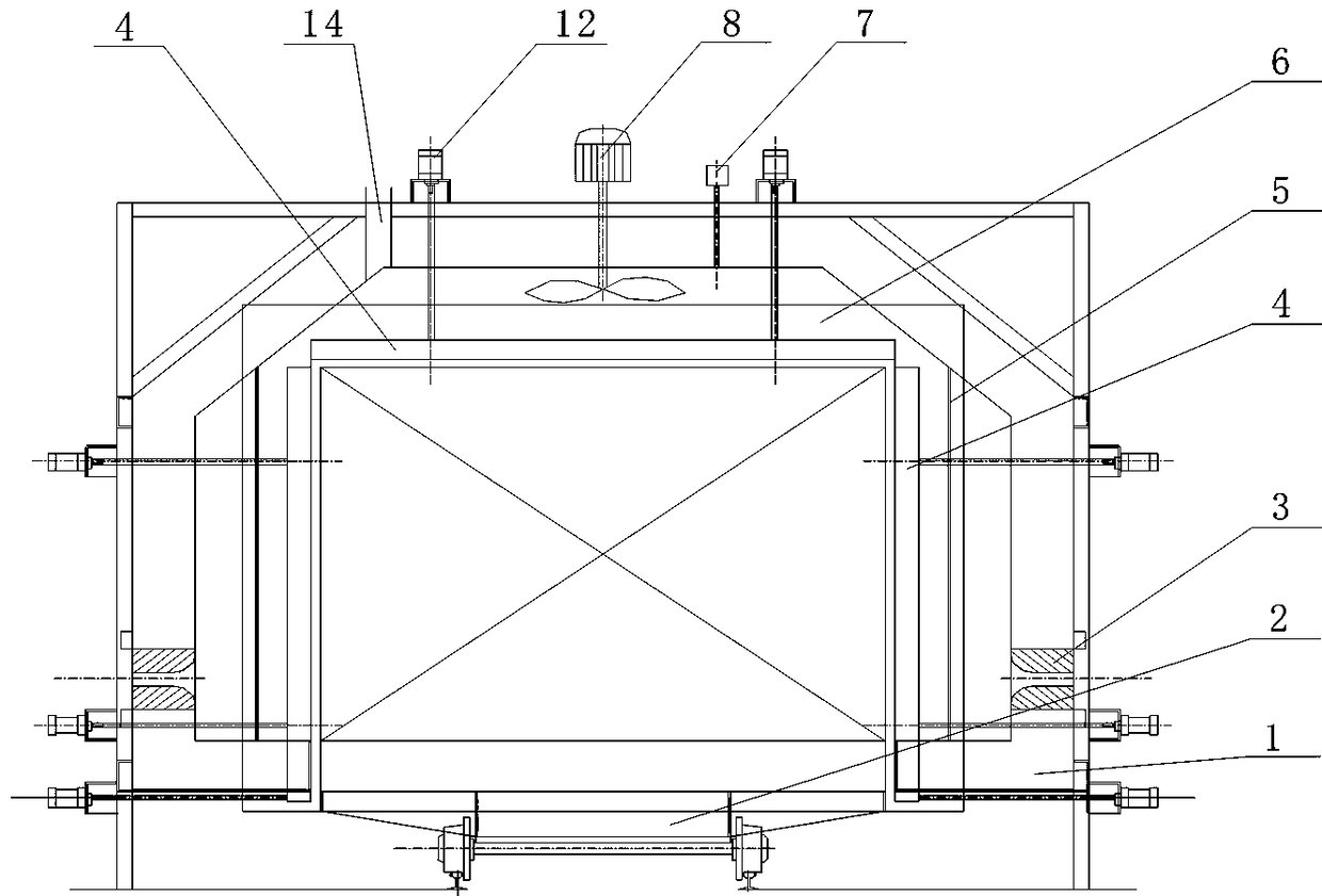
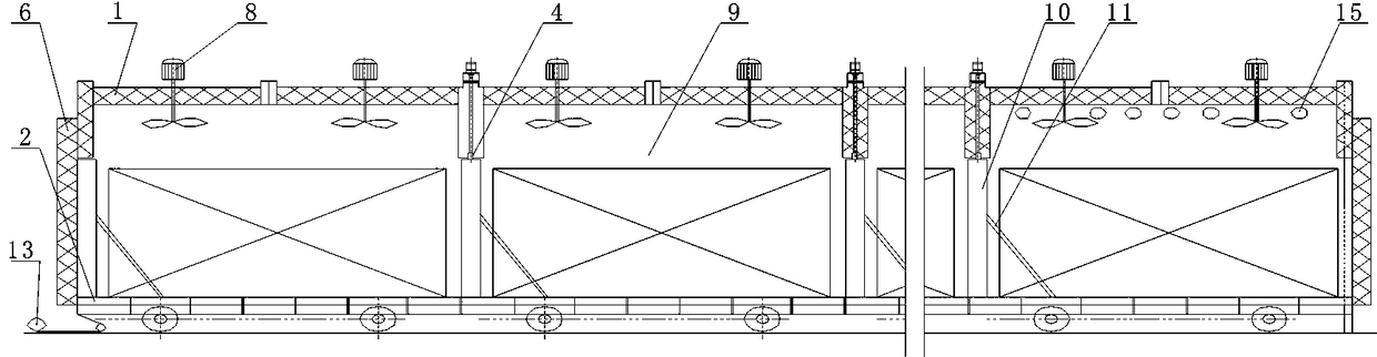
[0028] like Figure 1-2 As shown: the sub-area continuous tunnel kiln carbonization furnace described in this embodiment includes a furnace body 1, a trolley 2, a burner 3, a sealing plate 4, a heat radiation plate 5, a furnace door 6, a heat insulation plate 10 and a cylinder 12, The furnace body 1 is an airtight tunnel kiln structure, which is a strip structure, and the two ends are closed by the furnace door 6. The inside of the furnace body 1 is divided into a plurality of chambers matching the length of the trolley 2 by the sealing plate 4. The areas are respectively the drying area, the pre-carbonization area, the carbonization area and the cooling area. In this embodiment, there are nine areas, the purpose of which is to realize continuous production and ensure the quality of carb...


PUM


Abstract

The invention discloses a partitioned continuous tunnel kiln carbonization furnace. The carbonization furnace comprises a furnace body (1) and trolleys (2), wherein the furnace body (1) is of a closedtunnel kiln type structure, two ends of the furnace body (1) are closed by furnace doors (6), a plurality of areas matched with of the trolleys (2) in length are partitioned in the furnace body (1),each area and each trolley (2) form an independent closed area in the carbonization process, and a sealing plate (4), a heat radiation plate (5), a burner (3) and a byproduct outlet (14) are arrangedin each area of the furnace body (1). Continuous production is realized through partitioned carbonization, production efficiency is improved, identical substances are recycled in the same area, latertreatment is simplified and improved, biomass gas in carbonization is used for self-supplying gas, and production cost is further reduced.

Description

technical field [0001] The invention belongs to the technical field of carbonization equipment, and mainly relates to a sub-area continuous [0002] Tunnel kiln carbonization furnace is widely used in the carbonization of biomass. Background technique [0003] Biomass carbonization refers to the process of incomplete thermal degradation in the absence of an oxidizing atmosphere such as air to produce products (biomass charcoal) and by-products (water, wood vinegar, biomass gas and wood tar, etc.). Generally speaking, the biomass carbonization process needs to go through three stages: drying, pre-carbonization, and carbonization. The drying stage is the preparation stage for biomass carbonization. When the temperature reaches 120-150°C, the moisture contained in the biomass is heated first. Precipitate and become dry biomass; the pre-carbonization stage is the initial stage of carbonization of biomass. When the temperature reaches 150-275°C, the dry biomass is heated, and th...

Claims


Application Information

Patent Timeline
Patent Type & Authority Applications(China)
IPC IPC(8): C10B53/02C10B57/10C10B47/06C10B47/46
CPCC10B47/06C10B47/46C10B53/02C10B57/10Y02E50/10
Inventor 陈学锋
Owner 陈学锋
Why Eureka
Try Eureka