Cloth dyeing method for increasing cloth dip dyeing speed

A speed and cloth dyeing technology, applied in the field of textile printing and dyeing, can solve the problems affecting the quality of cloth, inconsistent speed, easy to stain clothes, etc., to achieve the effect of strengthening the effect of dipping, fast rotation speed, and realization of contact

Inactive Publication Date: 2018-10-12
张四通
View PDF1 Cites 1 Cited by
  • Summary
  • Abstract
  • Description
  • Claims
  • Application Information

AI Technical Summary

Problems solved by technology

[0002] In the process of dyeing cloth, the traditional method is to manually put the cloth into the dye vat, and then manually drag the other end of the cloth slowly for dip-dyeing. People directly contact with the dye, which is easy to stain the clothes. The dye contains many harmful substances. , it is easy to damage the health of workers, and the manual operation cannot evenly control the time of dyeing. Due to the inconsistent speed of different workers, the quality of the dyed cloth is not the same, and the dyeing is not uniform, which affects the quality of the whole batch of cloth, and the traditional method needs to be done manually. Stirring of the dye, uneven stirring, and when the concentration needs to be adjusted, it is necessary to manually pour the dye and water, and the concentration of the dye cannot be accurately grasped, so the announcement number: CN107661521A, publication date: in the patent document on February 06, 2018 A cloth dyeing machine with adjustable dye concentration is described, such as figure 1 As shown, it includes a frame, on which a cloth dyeing vat is installed, a bolt is provided on the top of the cloth dyeing vat, and the bolt is connected to the cover through a pin hole, and a cloth inlet and Cloth outlet, a cloth guide strip is placed in the cloth inlet, the left end of the cloth guide strip is connected with a cloth clip, the cloth clip holds the cloth, and the cloth dyeing cylinder is close to the cloth inlet and cloth outlet Cloth guide rods are respectively installed at the mouth, and a cloth clamping device is installed at the bottom of the cloth dyeing cylinder directly below the cloth guide rods, and a transmission shaft is installed on the frame at the right end of the cloth dyeing cylinder, and the transmission shaft passes through the belt and the motor. The output shaft is connected, the motor is connected to the controller, the right end of the cloth guide strip passes through the cloth guide rod, the cloth clamping device and the transmission shaft in turn, and the water source inlet and the dye inlet are provided on the cover. The water source inlet A water inlet pipe is connected, the dye inlet is connected to a hopper through a feed pipe, a rotating body is installed on the top of the cover, a stirring rod is connected to the bottom of the rotating body, an impeller is installed at the bottom end of the stirring rod, and an impeller is installed at the bottom of the cover. sensor installed
However, the agitating device in the above-mentioned patent document has the following defects: when the impeller rotates in a single direction, the dye therein has a certain rotational inertia, and it is difficult to fully contact and dip the cloth in the dyeing vat, resulting in low dyeing efficiency and poor dyeing efficiency. uniform

Method used


Image

  • Cloth dyeing method for increasing cloth dip dyeing speed
  • Cloth dyeing method for increasing cloth dip dyeing speed
  • Cloth dyeing method for increasing cloth dip dyeing speed

Examples


Embodiment 1

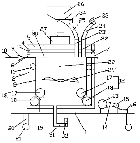
[0015] A cloth dyeing machine with adjustable dye concentration, a frame, a cloth dyeing vat, a driving motor and an intermittent drive mechanism, the cloth dyeing vat is arranged on the frame, and a stirring wing is arranged inside the dyeing vat, The driving motor is used to drive an intermittent driving mechanism, and the intermittent driving mechanism is used to provide intermittent driving force to realize the stirring blade has a rotating state and a static state within one rotation cycle.

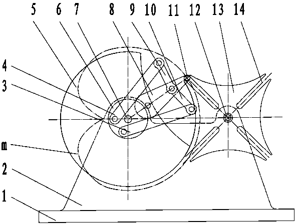
[0016] Such as figure 2 As shown, the intermittent drive mechanism includes a fixed plate 1, a support plate 2, a first long connecting rod 3, a second long connecting rod 4, a first engaging disc 5, a connecting rod fixing disc 6, a driving shaft 7, a rotating Arm 8, second short connecting rod 9, first short connecting rod 10, engaging pin shaft 11, driven shaft 12, second engaging disc 13 and bar-shaped engaging groove 14, the fixed plate 1 is fixedly arranged on On the frame, t...

Embodiment 2

[0019] A cloth dyeing machine with adjustable dye concentration, a frame, a cloth dyeing vat, a driving motor and an intermittent drive mechanism, the cloth dyeing vat is arranged on the frame, and a stirring wing is arranged inside the dyeing vat, The driving motor is used to drive an intermittent driving mechanism, and the intermittent driving mechanism is used to provide intermittent driving force to realize that the stirring blade has a rotating state and a static state within one rotation cycle.

[0020] Such as figure 2 As shown, the intermittent drive mechanism includes a fixed plate 1, a support plate 2, a first long connecting rod 3, a second long connecting rod 4, a first engaging disc 5, a connecting rod fixing disc 6, a driving shaft 7, a rotating Arm 8, second short connecting rod 9, first short connecting rod 10, engaging pin shaft 11, driven shaft 12, second engaging disc 13 and bar-shaped engaging groove 14, the fixed plate 1 is fixedly arranged on On the frame...


PUM


Abstract

The invention relates to a cloth dyeing method for increasing the cloth dip dyeing speed. The method is implemented through a dyeing machine. The dyeing machine comprises a rack, a cloth dyeing vat, adriving motor and an intermittent driving mechanism; the cloth dyeing vat is arranged on the rack, a stirring wing plate is arranged on the upper portion in the cloth dyeing vat, and the driving motor is used for driving the intermittent driving mechanism which is used for providing intermittent driving force so as to achieve the purpose that the stirring wing plate has the rotating state and thestationary state in a rotating period. When a clamping pin shaft on a rotating arm cooperates with strip-shaped clamping grooves, a second clamping disc is driven to rotate, and then the stirring wing plate is driven to rotate to make sufficient contact with cloth in the cloth dyeing vat; when the first clamping disc cooperates with a second arc-shaped groove, the second clamping disc is stationary; therefore, it is guaranteed that the stirring wing plate is stationary so that rotational inertia of dye is facilitated, and the dye can make more sufficient contact with the cloth.

Description

technical field [0001] The invention relates to the technical field of textile printing and dyeing, in particular to a cloth dyeing method for increasing the speed of cloth dyeing. Background technique [0002] In the process of dyeing cloth, the traditional method is to manually put the cloth into the dye vat, and then manually drag the other end of the cloth slowly for dip-dyeing. People directly contact with the dye, which is easy to stain the clothes. The dye contains many harmful substances. , it is easy to damage the health of workers, and the manual operation cannot evenly control the time of dyeing. Due to the inconsistent speed of different workers, the quality of the dyed cloth is not the same, and the dyeing is not uniform, which affects the quality of the whole batch of cloth, and the traditional method needs to be done manually. Stirring of the dye, uneven stirring, and when the concentration needs to be adjusted, it is necessary to manually pour the dye and wat...

Claims


Application Information

Patent Timeline
Patent Type & Authority Applications(China)
IPC IPC(8): D06B1/00D06B23/20D06B23/00
CPCD06B1/00D06B23/00D06B23/205
Inventor 张四通朱杰
Owner 张四通
Why Eureka
Try Eureka