Mass concrete temperature control system

A technology of mass concrete and temperature control system, applied in construction, infrastructure engineering and other directions, can solve the problems of poor control accuracy, time-consuming and laborious, and achieve the effect of solving time-consuming and laborious, reasonable structure and ingenious design.

Inactive Publication Date: 2018-10-12
山西六建集团有限公司
6 Cites 6 Cited by

AI-Extracted Technical Summary

Problems solved by technology

[0003] The present invention provides a large-volume concrete temperature control system in order to solve the problems of time-consum...

Abstract

The invention relates to a mass concrete temperature control technology, in particular to a mass concrete temperature control system. The mass concrete temperature control system solves the problems that in the control process of an existing mass concrete temperature control technology, time and labor are consumed, and the control precision is poor. The mass concrete temperature control system comprises a mass concrete pouring body arranged in a curing shed inner cavity, an executing portion, a control portion and a power supply portion; the executing portion comprises a water storing pond, acirculating pump, M electrical valves, M cooling water pipes and a humidifying device; M is a positive integer; the control portion comprises N sensor installing barrels, N sets of inner temperature sensors, an outer temperature sensor, an outer humidity sensor, an upper computer and a wireless transmission module; N is a positive integer; and a power supply system comprises a solar panel, a storage battery and an inverter. The mass concrete temperature control system is applicable to mass concrete temperature control.

Application Domain

Technology Topic

Image

  • Mass concrete temperature control system
  • Mass concrete temperature control system
  • Mass concrete temperature control system

Examples

  • Experimental program(1)

Example Embodiment

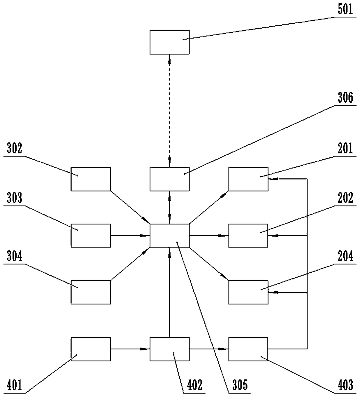
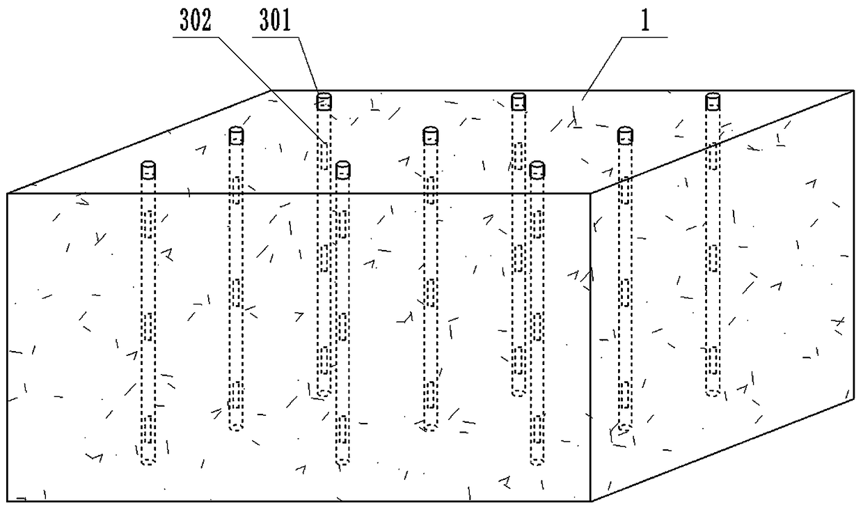
[0019] A large-volume concrete temperature control system, including a large-volume concrete pouring body 1 arranged in the inner cavity of a curing shed, an execution part, a control part, and a power supply part;
[0020] The execution part includes a water storage tank, a circulating pump 201, M electric valves 202, M cooling water pipes 203, and a humidifying device 204; M is a positive integer;
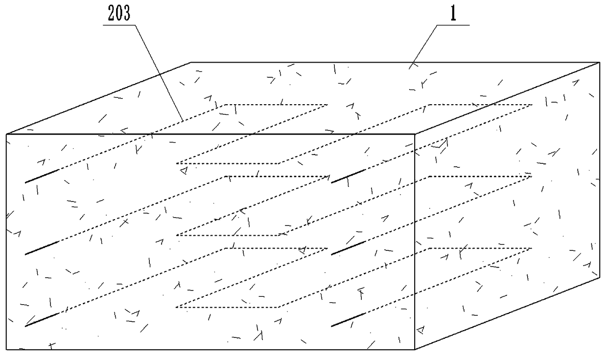
[0021] The water inlet of the circulating pump 201 is connected to the water storage tank; each cooling water pipe 203 is in the shape of a square wave; each cooling water pipe 203 is buried horizontally inside the large-volume concrete pouring body 1, and each cooling water pipe 203 is equally spaced and parallel from top to bottom arrangement; the water inlet and the water outlet of each cooling water pipe 203 all extend to the outside of the mass concrete pouring body 1; the water inlet of each cooling water pipe 203 communicates with the water outlet of the circulation pump 201 through each electric valve 202; the water outlet of each cooling water pipe 203 The water outlets are all connected to the water storage tank; the output port of the humidifying device 204 is connected to the inner cavity of the curing shed;
[0022] The control part includes N sensor mounting cylinders 301, N groups of internal temperature sensors 302, external temperature sensors 303, external humidity sensors 304, host computer 305, and wireless transmission module 306; N is a positive integer;
[0023] Each sensor installation cylinder 301 is buried vertically inside the large-volume concrete pouring body 1, and each sensor installation cylinder 301 is arranged in a rectangular array; the lower end of each sensor installation cylinder 301 is closed, and the upper end is provided with an opening; each sensor The upper opening of the installation cylinder 301 extends to the outside of the mass concrete pouring body 1; each group of internal temperature sensors 302 includes a number of internal temperature sensors 302 arranged equidistantly from top to bottom; each group of internal temperature sensors 302 one by one Correspondingly installed in the inner cavity of each sensor installation tube 301; the external temperature sensor 303 and the external humidity sensor 304 are all installed in the inner cavity of the maintenance shed; the signal input end of the host computer 305 is connected with the signal output end, The signal output end of the external temperature sensor 303 and the signal output end of the external humidity sensor 304 are connected; The input terminal is connected; the wireless transmission module 306 is bidirectionally connected with the upper computer 305;
[0024] The power supply system includes a solar panel 401, a storage battery 402, and an inverter 403;
[0025] The output end of the solar panel 401 is connected with the input end of the storage battery 402; the output end of the storage battery 402 is connected with the power supply end of the upper computer 305 and the input end of the inverter 403 respectively; the output end of the inverter 403 is respectively connected with the circulation pump 201 The power supply terminal, the power supply terminal of each electric valve 202, and the power supply terminal of the humidifying device 204 are connected.
[0026] During specific implementation, the signal output terminals of each group of internal temperature sensors 302 are led out through the upper openings of the sensor mounting cylinders 301 in a one-to-one correspondence. The wireless transmission module 306 is a GPRS wireless transmission module. The solar panel 401 is a monocrystalline silicon solar panel. The curing shed is a steam curing shed; the humidifying device is a steam generator.

PUM

no PUM

Description & Claims & Application Information

We can also present the details of the Description, Claims and Application information to help users get a comprehensive understanding of the technical details of the patent, such as background art, summary of invention, brief description of drawings, description of embodiments, and other original content. On the other hand, users can also determine the specific scope of protection of the technology through the list of claims; as well as understand the changes in the life cycle of the technology with the presentation of the patent timeline. Login to view more.

Similar technology patents

Classification and recommendation of technical efficacy words

  • Reasonable structure
  • Ingenious design

A ceramic insulator device for high voltage capacitor

InactiveCN101546636ALow manufacturing costReasonable structureSuspension/strain insulatorsHigh voltage capacitorsEngineering
Owner:王海龙
Why Eureka
Try Eureka