Multifunctional vehicle carrier

A car mover, multi-functional technology, applied in the direction of buildings, building types, buildings, etc. where cars are parked, can solve the problems of difficult car handling, no anti-collision device, difficult car positioning, etc., to achieve simple structure and avoid sideslip , The effect of convenient transportation

Pending Publication Date: 2018-10-12
NANJING CHEERLIFE INTELLIGENT TRANSPORTATION CO LTD
View PDF5 Cites 3 Cited by
  • Summary
  • Abstract
  • Description
  • Claims
  • Application Information

AI Technical Summary

Problems solved by technology

[0004] The object of the present invention is to provide a kind of multifunctional vehicle carrier, to solve the problem that the structure of the vehicle carrier proposed in the above-mentioned background technology is complicated, it is difficult to carry the car, it is difficult to locate the car and there is no anti-collision device

Method used


Image

  • Multifunctional vehicle carrier
  • Multifunctional vehicle carrier
  • Multifunctional vehicle carrier

Examples


Embodiment 1

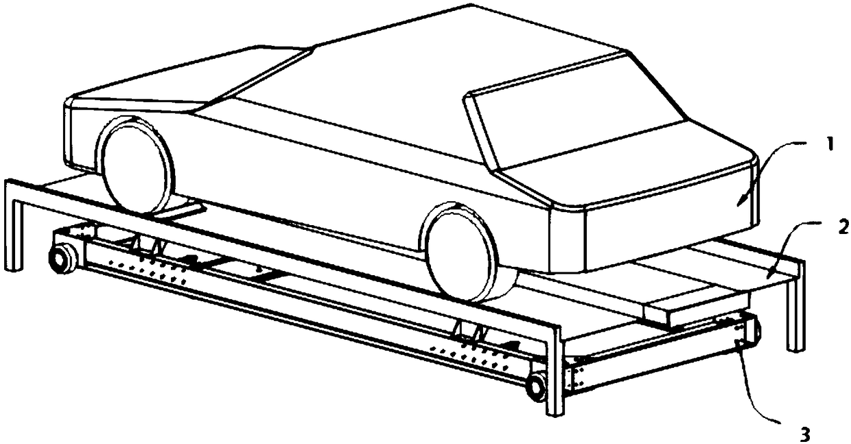
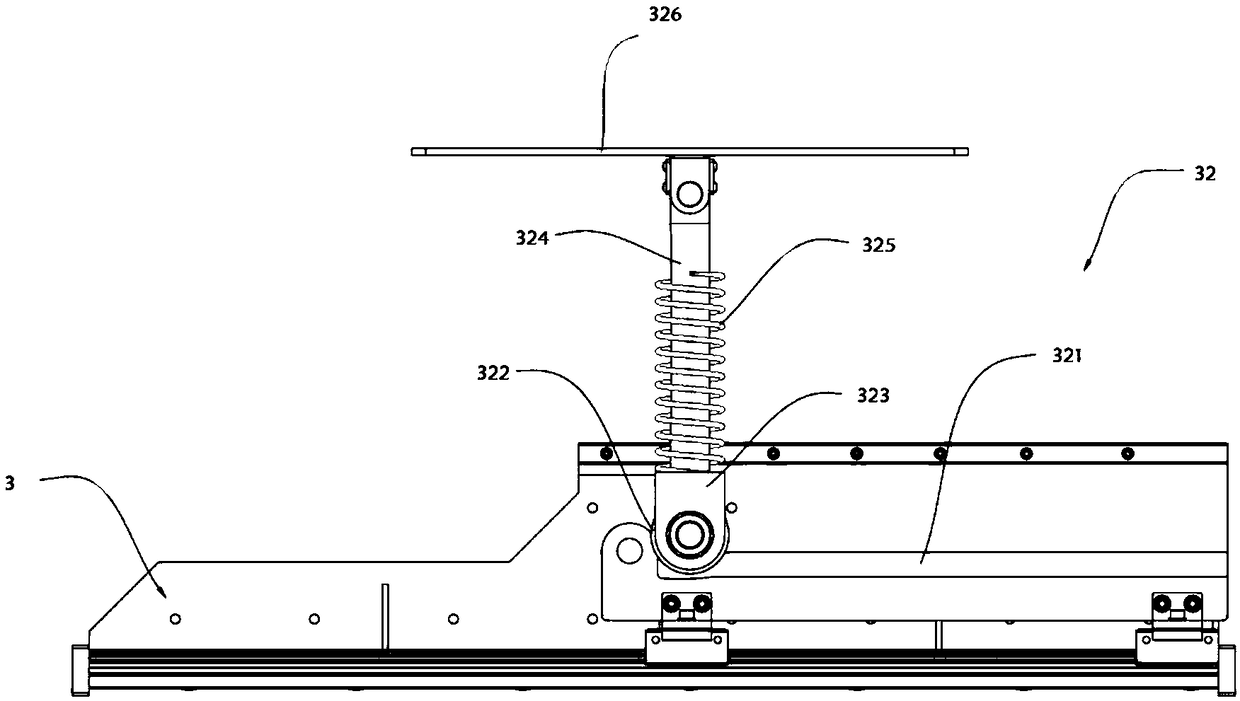
[0032] A multifunctional vehicle carrier such as Figure 1 to Figure 3 As shown, it includes a vehicle body 1, a vehicle-mounted board 2 for placing the vehicle body 1, and a mobile plate 3 installed on the bottom of the vehicle-mounted board 2. Steering wheels 31 are arranged around the bottom of the mobile board 3, and the inner wall of the mobile board 3 is provided with several A handling device 32, the handling device 32 includes a slide rail 321 installed on the inner wall of the mobile plate 3, the inside of the slide rail 321 is provided with a pulley 322, the outer wall of the pulley 322 is provided with a mounting seat 323, and the top of the mounting seat 323 is provided with a push rod 324 The outer wall of the push rod 324 is provided with a damping spring 325, the top of the push rod 324 is provided with a top plate 326, and the pulley 322 is slidably connected to the slide rail 321.

[0033] In this embodiment, the slide rail 321 and the inner wall of the moving...

Embodiment 2

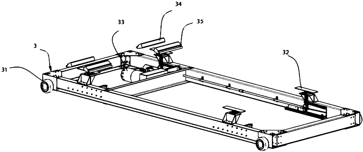
[0037] In the specific implementation process, in order to facilitate the handling of the vehicle-mounted board 2, the inventors improved the mobile board 3, as a preferred embodiment, as Figure 4 As shown, the inside of the moving plate 3 is provided with a driving motor 33, and one end of the driving motor 33 is provided with a speed reducer 331, and both sides of the speed reducer 331 are equipped with an output shaft 332, and one end of the output shaft 332 is provided with a bevel gear 333. One end of the tooth 333 is provided with a lead screw 334, and the surface of the lead screw 334 is provided with a nut 335, the bevel teeth 333 mesh with the lead screw 334, and the nut 335 and the mounting seat 323 are welded and fixed.

[0038] In this embodiment, the drive motor 33 adopts the servo motor model ISMH1-40B30CB produced by Dongguan Fengpin Automation Co., Ltd., its rated voltage is 220V, its speed response frequency is 3000KHz, and its power is 0.4KW. Provided by the...

Embodiment 3

[0042] In the specific implementation process, in order to limit the position of the vehicle during transportation, the inventors improved the structure of the vehicle board 2, as a preferred embodiment, such as Figure 5 and Figure 6 As shown, one end of the vehicle-mounted board 2 is provided with an anti-collision device 21, and the bottom of the vehicle-mounted board 2 is provided with struts 22 around, and the surface of the vehicle-mounted board 2 is provided with a wheel groove 23, and the surface of the vehicle-mounted board 23 is provided with a limiting groove 24. The vehicle board 2 is provided with a mounting groove 25 near the bottom side of the limiting groove 24, the inside of the limiting groove 24 is provided with a wheel limiting block 34, and one end of the wheel limiting block 34 is provided with a connecting shaft 35, and the wheel limiting block 34 and The top plate 326 is welded and fixed, and the connecting shaft 35 is rotatably connected to the mounti...


PUM


Abstract

The invention relates to the technical field of stereo parking devices, in particular to a multifunctional vehicle carrier. The multifunctional vehicle carrier comprises a vehicle body, a vehicle carrying plate used for carrying the vehicle body, and a moving plate mounted at the bottom of the vehicle carrying plate. A carrying device comprises sliding rails arranged on the inner wall of the moving plate; the sliding rails are internally provided with sliding wheels; conical teeth are arranged one ends of output shafts; lead screws are arranged at one ends of the conical teeth; wheels groovesare formed in the surface of the vehicle carrying plate; limiting grooves are formed in the surfaces of the wheel grooves; and a contact switch is arranged on the inner wall of an outer shell. According to the multifunctional vehicle carrier, wheel limiting blocks are arranged for increasing resistance between the wheels and the vehicle carrying plate, and sideslip is avoided; the conical teeth are used for changing the rotating direction of the output shafts, further an installation seat is pushed to drive the sliding wheels to slide in the sliding rails; the structure is simple, installationis convenient, and therefore carrying work is convenient; and the contact switch is arranged for starting and stopping a whole circuit, and therefore installation of the overall operation is improved.

Description

technical field [0001] The invention relates to the technical field of three-dimensional parking equipment, in particular to a multifunctional vehicle carrier. Background technique [0002] The problem of nowhere to park vehicles is the result of the city's social, economic, and traffic development to a certain extent. The development of three-dimensional parking equipment has a history of nearly 30 to 40 years abroad, especially in Japan. All of the above have been successful. my country also began to research and develop mechanical three-dimensional parking equipment in the early 1990s, which has a history of nearly twenty years. [0003] The structure of the vehicle carrier in the prior art is complicated, it is difficult to carry the car, it is difficult to locate the car, and the car tends to slip during the handling process, and the existing car carrier does not have an anti-collision device. In view of this, we propose a multifunctional vehicle carrier. Contents o...

Claims


Application Information

Patent Timeline
Patent Type & Authority Applications(China)
IPC IPC(8): E04H6/42E04H6/12
CPCE04H6/12E04H6/42
Inventor 金龙飞
Owner NANJING CHEERLIFE INTELLIGENT TRANSPORTATION CO LTD
Why Eureka
Try Eureka