Gas stove

A gas furnace and flue gas technology, applied in air heaters, greenhouse gas reduction, climate sustainability, etc., can solve problems such as easy generation of more condensed water

Pending Publication Date: 2018-10-12
GREE ELECTRIC APPLIANCES INC
View PDF0 Cites 2 Cited by
  • Summary
  • Abstract
  • Description
  • Claims
  • Application Information

AI Technical Summary

Problems solved by technology

[0004] The embodiment of the present invention provides a gas furnace to solve the technical problem in the prior art

Method used


Image

  • Gas stove

Examples


Embodiment Construction

[0018] In order to make the object, technical solution and advantages of the present invention clearer, the present invention will be described in further detail below in conjunction with the embodiments and accompanying drawings. Here, the exemplary embodiments and descriptions of the present invention are used to explain the present invention, but not to limit the present invention.

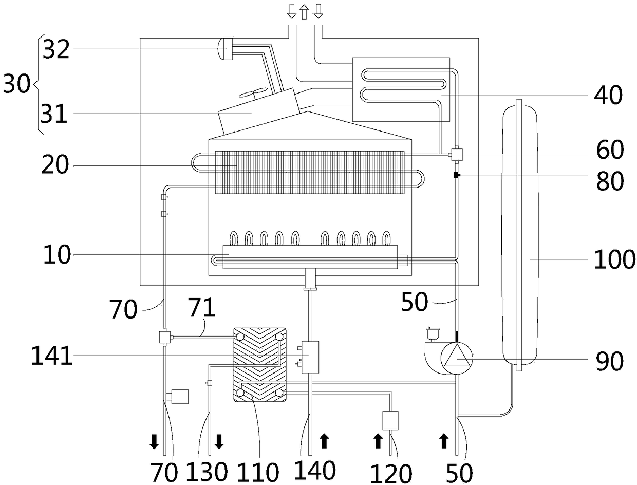
[0019] figure 1 An embodiment of a gas furnace of the present invention is shown comprising a burner assembly 10 , a primary heat exchanger 20 , a flue gas absorption assembly 30 and a secondary heat exchanger 40 . The primary heat exchanger 20 is arranged in the combustor assembly 10 group for absorbing combustion heat. The smoke absorbing assembly 30 is connected with the burner assembly 10 and used for absorbing the smoke generated by the burner assembly 10 . The secondary heat exchanger 40 is arranged in the flue gas absorption assembly 30 for absorbing flue gas heat. The gas furnace als...


PUM


Abstract

The invention provides a gas stove. The gas stove comprises a burner assembly, a first-stage heat exchanger, a smoke absorbing assembly and a second-stage heat exchanger, wherein the first-stage heatexchanger is arranged in the burner assembly; the smoke absorbing assembly is connected to the burner assembly; the second-stage heat exchanger is arranged in the smoke absorbing assembly. The gas stove further comprises a water returning pipeline, a three-way valve, a heat supplying pipeline and a temperature detector; the water returning pipeline is correspondingly connected to a water inlet ofthe second-stage heat exchanger and a water inlet of the first-stage heat exchanger through the three-way valve; the temperature detector is used for detecting the water temperature of the water returning pipeline; and the controller is electrically connected to the temperature detector and the three-way valve. According to the technical scheme, the gas stove is capable of preventing smoke temperature from decreasing to be less than dew point temperature to generate a large number of condensate water through low-temperature in the water returning pipeline, and thus a smoke pipe is prevented from serious corrosion by excessive condensate water; and moreover, the potential risk caused by icing of the condensate water at an outlet of the smoke pipe can be solved.

Description

technical field [0001] The invention relates to the technical field of gas equipment, in particular to a gas furnace. Background technique [0002] In order to improve the thermal efficiency of the condensing gas wall-hung boiler, the high-temperature flue gas generated will be reused. By exchanging heat with the high-temperature flue gas through the return line, the heat of the high-temperature flue gas can be utilized. [0003] However, the above waste heat utilization method will reduce the temperature of the flue gas, and when the temperature of the flue gas is lower than the dew point temperature, the water vapor therein will condense into condensed water. The condensed water formed in the smoke tube will cause serious corrosion to the smoke tube. When the ambient temperature is low, the condensed water is also easy to freeze at the outlet of the smoke pipe, forming ice blades, and there is a safety hazard that the ice blades will fall when installed in high-rise buil...

Claims


Application Information

Patent Timeline
IPC IPC(8): F24H8/00F24H9/20F23J15/06
CPCF23J15/06F24H8/00F24H9/2035Y02B30/00Y02E20/30
Inventor 马曾文张坚伏张霞梁桂源郭特特
Owner GREE ELECTRIC APPLIANCES INC
Why Eureka
Try Eureka