Rear projection augmented reality display system capable of eliminating bright spots
An augmented reality and display system technology, applied in optics, magnifying glass, instruments, etc., can solve the problems of losing virtual screen information, reducing user experience, etc., and achieve the effect of reducing volume and solving discomfort
- Summary
- Abstract
- Description
- Claims
- Application Information
AI Technical Summary
Problems solved by technology
Method used
Image

Examples
Embodiment 1
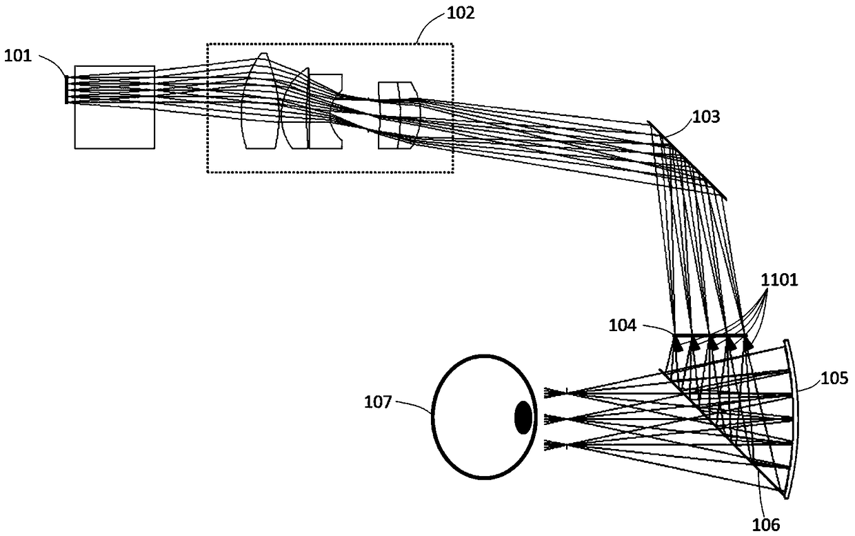
[0052] The optical path structure of the rear projection projection augmented reality display system of this embodiment is as follows: figure 1 As shown, the rear projection augmented reality display system includes a microdisplay 101 , a projection lens set 102 , a 45-degree flat mirror 103 , a rear projection screen 104 , an eyepiece 105 and a transflective panel 106 .
[0053] The micro-display 101 and the projection lens group 102 form an off-axis system (that is, the micro-display 101 is not on the optical axis of the projection lens group 102), and finally the virtual information projected on the micro-display 101 (that is, the information generated by the micro-display for augmented reality) Image light) is obliquely incident on the rear projection screen 104 after being bent by the 45-degree plane reflector 103. The rear projection screen 104 forward-scatters the incident light, and its scattering characteristics have nothing to do with the angle of the incident light,...
Embodiment 2
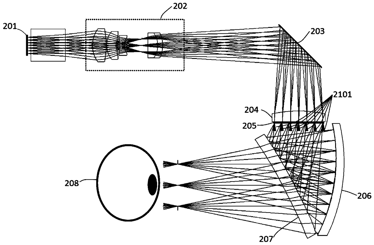
[0063] The optical path structure of the rear projection projection augmented reality display system of this embodiment is as follows: figure 2 As shown, the rear projection augmented reality display system includes a microdisplay 201 , a projection lens set 202 , a 45-degree flat mirror 203 , a field lens 204 , a rear projection screen 205 , a first eyepiece 206 and a second eyepiece 207 .
[0064] The virtual information projected on the micro-display 201 (that is, image light for augmented reality) is projected by the projection lens group 202 and deflected by the 45-degree flat reflector 203 before being incident on the field lens 204 . The function of the field lens 204 is to change the direction of the principal ray of projection light in each field of view, so that the principal ray of projection light in each field of view is incident vertically on the rear projection screen 205 . The rear projection screen 205 forward-scatters the incident light, its scattering chara...
Embodiment 3
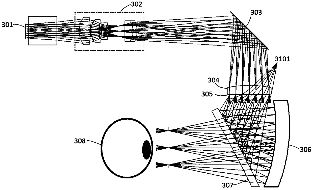
[0072] The optical path structure of the rear projection projection augmented reality display system of this embodiment is as follows: image 3 As shown, the rear projection augmented reality display system includes a microdisplay 301 , a projection lens set 302 , a 45-degree flat mirror 303 , a field lens 304 , a rear projection screen 305 , a first eyepiece 306 and a second eyepiece 307 .
[0073] The positional relationship of each part is the same as that of Embodiment 2, and the difference from Embodiment 2 lies in the first eyepiece 306 and the second eyepiece 307 . The surface shapes of the first eyepiece and the second eyepiece in Embodiment 2 satisfy an odd polynomial, and the surface shapes of the first eyepiece and the second eyepiece in Embodiment 2 satisfy an XY polynomial.
[0074] Table 3 is the data sheet of the rear projection augmented reality display system of this embodiment. The exit pupil diameter of this embodiment is 10 mm, the exit pupil distance is 16...
PUM
| Property | Measurement | Unit |
|---|---|---|
| Full field of view | aaaaa | aaaaa |
Abstract
Description
Claims
Application Information
 - R&D
- Intellectual Property
- Life Sciences
- Materials
- Tech Scout
- Unparalleled Data Quality
- Higher Quality Content
- 60% Fewer Hallucinations
Browse by: Latest US Patents, China's latest patents, Technical Efficacy Thesaurus, Application Domain, Technology Topic, Popular Technical Reports.
© 2025 PatSnap. All rights reserved.Legal|Privacy policy|Modern Slavery Act Transparency Statement|Sitemap|About US| Contact US: help@patsnap.com