
Spatial positioning method based on vision

A spatial positioning and vision technology, applied in image data processing, instruments, calculations, etc., can solve the problems of high equipment requirements, slow speed, complex operation, etc., and achieve the effect of high calibration accuracy, simple equipment, and low algorithm complexity.

Active Publication Date: 2018-10-12
INST OF INFORMATION ENG CAS
View PDF12 Cites 14 Cited by
  • Summary
  • Abstract
  • Description
  • Claims
  • Application Information

AI Technical Summary

Problems solved by technology

[0004] The main purpose of the present invention is to provide a space positioning method based on square labels and vision, which can solve the problems of slow speed, low precision, complicated operation and high equipment requirements of the current space positioning method

Method used


Image

  • Spatial positioning method based on vision
  • Spatial positioning method based on vision
  • Spatial positioning method based on vision

Examples


Embodiment Construction

[0047] The technical solutions in the embodiments of the present invention will be clearly and completely described below in conjunction with the drawings in the embodiments of the present invention.

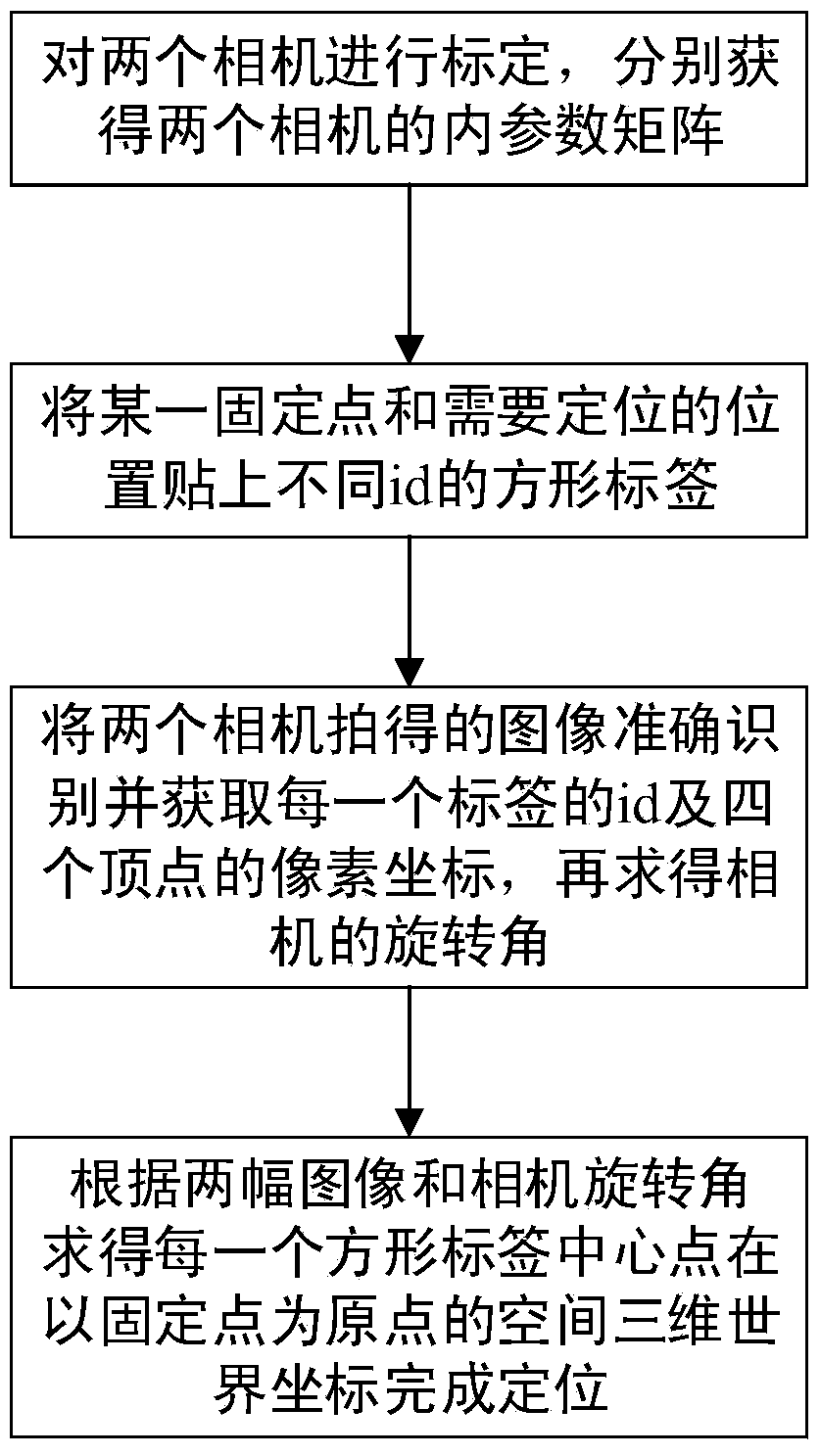
[0048] refer to figure 1 and image 3 , in one embodiment, the vision-based spatial positioning method provided, the specific steps are as follows:

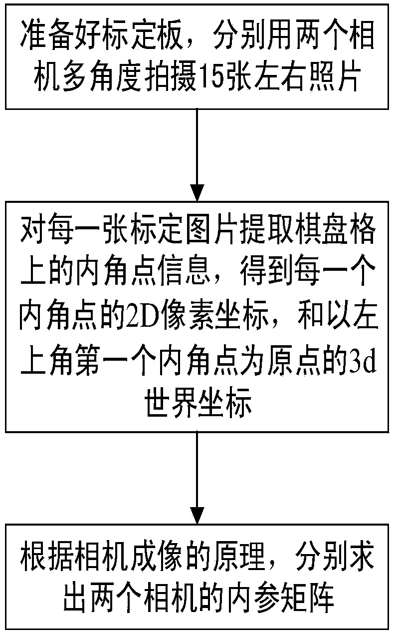
[0049] 1) Calibrate the two cameras, and obtain the internal parameter matrices of the two cameras (the distortion coefficients are in the internal parameter matrix);

[0050] 2) Set square labels with different ids at a fixed point and a position to be positioned; more commonly, set square labels by pasting.

[0051] The above-mentioned square label is a pattern similar to a two-dimensional code, and each label corresponds to a unique id number and pattern arrangement, and the program can recognize this label and obtain the corresponding id.

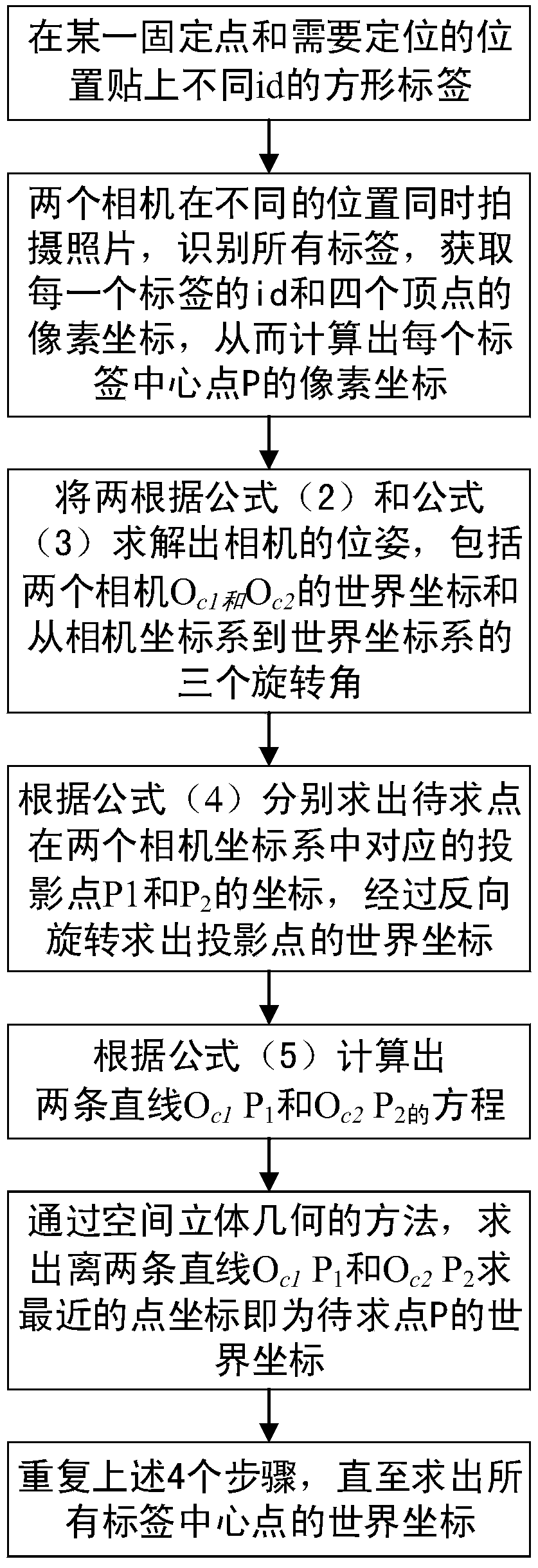
[0052] 3) Obtain the id of each label and the pixel coordinates of the four vertices ...


PUM


Abstract

The invention provides a spatial positioning method based on square label and vision, comprising the following steps: obtaining inner parameter matrices of two cameras by calibration; setting square labels with different ids at a certain fixed point and a position to be located; using the two cameras to shoot the square labels at the fixed point and the position to be located simultaneously, obtaining the coordinate information of each square label, and obtaining a three-dimensional world coordinate with the fixed point as an original point and three rotating angles from a camera coordinate system to the three-dimensional world coordinate system of the two cameras according to the coordinate information and the inner parameter matrices; and obtaining a three-dimensional world coordinate ofeach square label central point with the fixed point as the original point according to the three-dimensional world coordinate with the fixed point as an original point and the three rotating anglesfrom a camera coordinate system to the three-dimensional world coordinate system of the two cameras, which can solve the problems of slow speed, low precision, complicated operation and high equipmentrequirements of the current spatial positioning method.

Description

technical field [0001] The invention relates to the fields of digital image processing and computer vision, in particular to a method and system for accurately positioning the world coordinates of any point in space, which belongs to space positioning technology, and is especially suitable for robot positioning and industrial automation production. Background technique [0002] In recent years, artificial intelligence has developed rapidly, and has even become an important factor for countries all over the world to compete for technological power. As an important branch in the field of artificial intelligence, computer vision technology has attracted the attention of many researchers. Vision-based spatial positioning techniques have also been applied to a large number of machine vision systems. Space positioning technology is widely used, including robot positioning, industrial automation production, monitoring, engineering surveying and mapping, military aerospace and othe...

Claims


Application Information

Patent Timeline
IPC IPC(8): G06T7/80
CPCG06T7/85
Inventor 葛仕明刘文瑜赵胜伟
Owner INST OF INFORMATION ENG CAS
Learn More