
Anti-resonant three-phase four-wire type voltage transformer for ring network cabinet

A technology of voltage transformer and ring main unit, applied in the direction of inductor, transformer/inductor shell, transformer/inductor magnetic core, etc., can solve the problem that cannot guarantee the reliable operation of secondary monitoring and relay protection equipment, and cannot effectively measure And monitoring voltage parameters, can not effectively suppress the resonance situation and other problems, to prevent oversaturation, increase overvoltage capability, reduce the effect of no-load current

Pending Publication Date: 2018-10-12
湖北大二互科技股份有限公司
View PDF5 Cites 0 Cited by
  • Summary
  • Abstract
  • Description
  • Claims
  • Application Information

AI Technical Summary

Problems solved by technology

[0002] The operating parameters in the modern urban power grid are complex, there are a large number of harmonics, the unbalance of three-phase loads and other problems, the voltage parameters cannot be effectively measured and monitored, and there are harms caused by harmonics. In complex operating conditions, the measurement cannot be guaranteed, and cannot Effectively suppress various resonance conditions, and cannot guarantee the reliable operation of secondary monitoring and relay protection equipment

Method used


Image

  • Anti-resonant three-phase four-wire type voltage transformer for ring network cabinet
  • Anti-resonant three-phase four-wire type voltage transformer for ring network cabinet
  • Anti-resonant three-phase four-wire type voltage transformer for ring network cabinet

Examples


Embodiment Construction

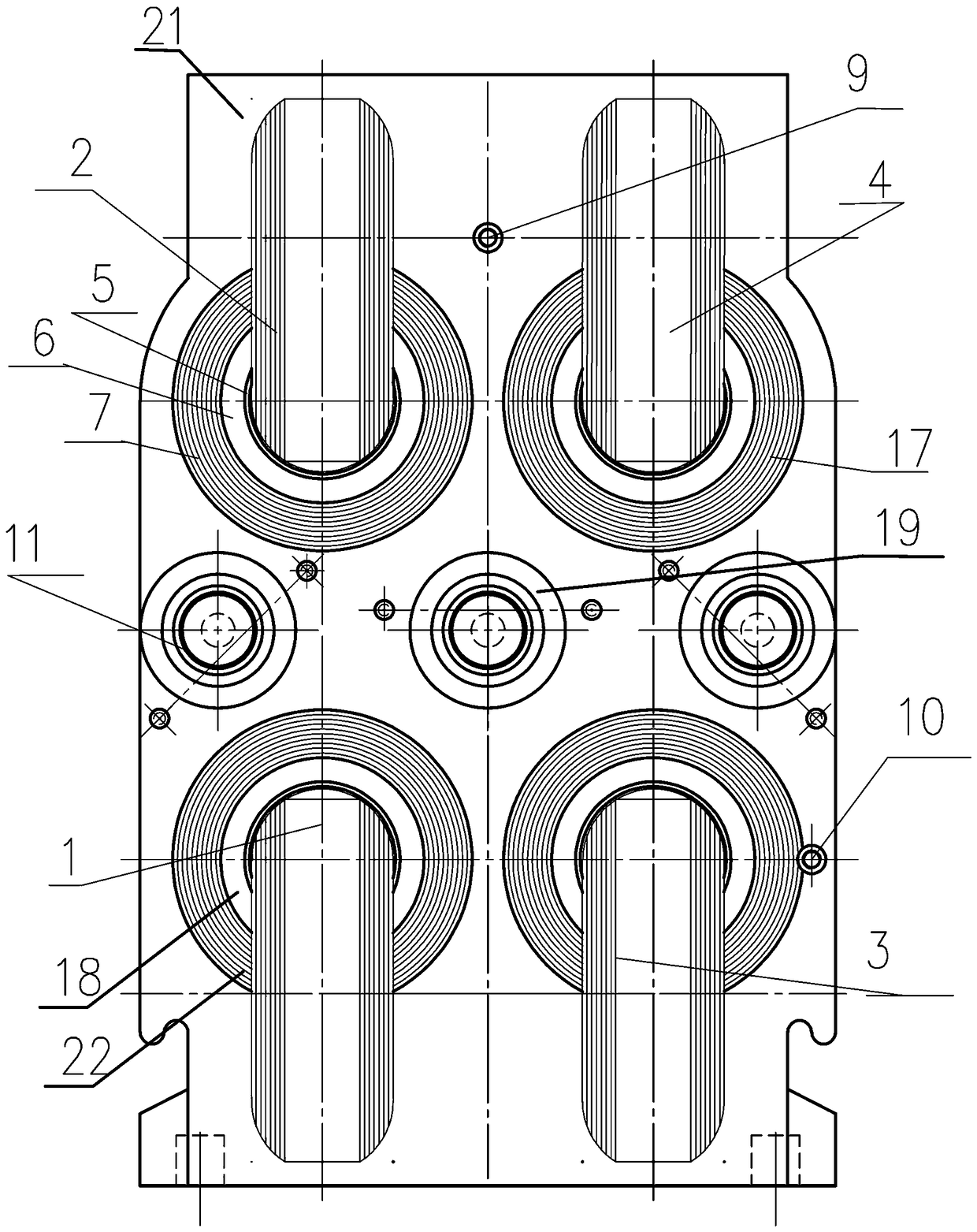
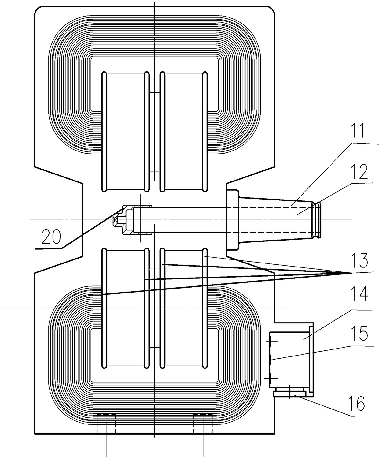
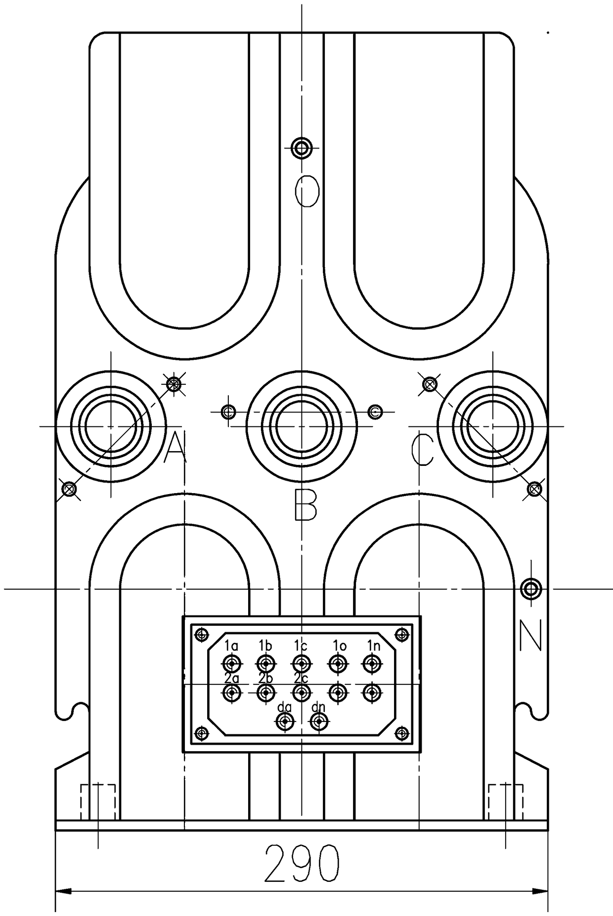
[0036] The anti-resonance three-phase four-wire voltage transformer for the ring network cabinet includes an insulating shell 21 .

[0037] The insulating shell 21 is provided with an A-phase annular iron core 1 , a B-phase annular iron core 2 , a C-phase annular iron core 3 and a zero-sequence annular iron core 4 .

[0038] The four iron cores are all arranged vertically, two by two are located on the upper floor, arranged left and right, and two by two are located on the lower floor, arranged left and right.

[0039] The two adjacent iron cores left and right are parallel to each other, and the two adjacent iron cores up and down are on a vertical line.

[0040] Phase B annular iron core 2 is located on the upper left side, and zero-sequence annular iron core 4 is located on the upper right side.

[0041] The A-phase toroidal core 1 is located on the lower left side, and the C-phase toroidal core 3 is located on the lower right side.

[0042] B-phase annular iron core 2 is...


PUM


Abstract

The invention provides an anti-resonant three-phase four-wire type voltage transformer for a ring network cabinet. The anti-resonant three-phase four-wire type voltage transformer comprises A, B, C and zero-sequence annular iron cores. Each two of the four iron cores are located on an upper layer and are arranged on the left and right sides, and each two of the four iron cores are located on a lower layer and are arranged on the left and right sides. Two B-phase secondary windings are wound on the B-phase iron core, and a primary winding is coaxially wound on the outer sides of the two B-phasesecondary windings. The A, C and zero-sequence structures are the same, the primary windings of the B, A and C phases are connected in a star shape, a neutral point is led out to a neutral point O-phase end, and the neutral point of the primary winding is also connected to a grounding end N end through a zero-sequence primary winding. 6 secondary windings of the B, A and C phases are connected ina star shape, the neutral point is grounded through a zero-sequence first secondary winding. Secondary output terminals are led out from the 6 secondary windings of the B, A and C phases. The two ends of a zero-sequence second secondary winding are led out to a secondary output terminal. A grading ring is arranged at the outside of the primary winding. Voltage parameters are effectively metered and monitored, the harmonic hazards are inhibited, and the metering, the secondary monitoring and the reliable operation of the relay equipment are ensured under complex operation conditions.

Description

technical field [0001] The invention belongs to the field of voltage transformers, in particular to an anti-resonance three-phase four-wire voltage transformer for a ring network cabinet. Background technique [0002] The operating parameters in the modern urban power grid are complex, there are a large number of harmonics, the unbalance of three-phase loads and other problems, the voltage parameters cannot be effectively measured and monitored, and there are harms caused by harmonics. In complex operating conditions, the measurement cannot be guaranteed, and cannot Effective suppression of various resonance conditions cannot guarantee the reliable operation of secondary monitoring and relay protection equipment. Contents of the invention [0003] The object of the present invention is to provide an anti-resonance three-phase four-wire voltage transformer for a ring network cabinet. The voltage transformer can effectively measure and monitor voltage parameters and suppress...

Claims


Application Information

Patent Timeline
Patent Type & Authority Applications(China)
IPC IPC(8): H01F27/26H01F27/28H01F27/30H01F27/24H01F27/02H01F38/38
CPCH01F27/022H01F27/24H01F27/266H01F27/2895H01F27/306H01F38/38
Inventor 王维贤王峰董国鹏姚伟钱青
Owner 湖北大二互科技股份有限公司
Learn More