Hidden antenna structure for underground communication

A technology of hidden antenna and underground communication, applied in the field of hidden antenna structure, can solve the problems of unable to achieve normal operation, poor signal, inconvenient operation and management of cable tunnels, etc.

Pending Publication Date: 2018-10-12
CHANGLAN CABLE ACCESSORIES
View PDF4 Cites 0 Cited by
  • Summary
  • Abstract
  • Description
  • Claims
  • Application Information

AI Technical Summary

Problems solved by technology

[0003] However, due to obstacles such as soil, concrete, steel mesh, and manhole covers, there is usually no good wireless network coverage in power tunnels and joint shafts, so wireless communication products used in power tunnels are usually not available due to poor signals. To achieve normal work, which brings great inconvenience to the operation and management of the cable tunnel

Method used


Image

  • Hidden antenna structure for underground communication
  • Hidden antenna structure for underground communication

Examples


Embodiment 1

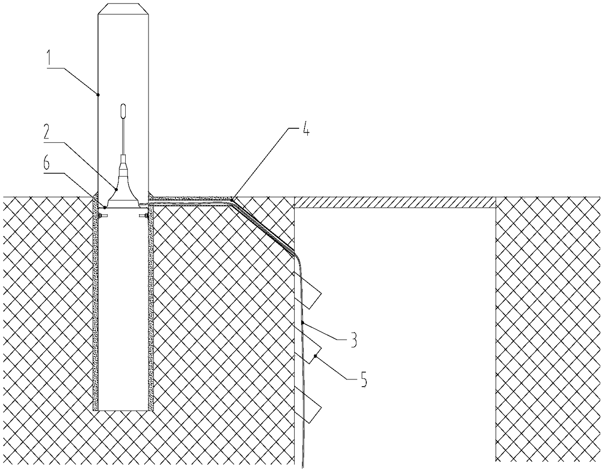
[0027] Such as figure 1 , the hidden antenna structure for underground communication, including cable marker pile 1 suction cup antenna 2 antenna extension wire 3. The cable marker pile is made of PVC material, fully insulated, corrosion-resistant, high mechanical strength, no recycling value, both environmental protection and safety; the cable marker pile is installed on the ground surface near the cable tunnel or the wellhead of the joint well, the cable marker pile is fixed on the ground surface through concrete, and a C-shaped bracket 6 is arranged inside the cable marker pile, and the type bracket and There are two types of fixed connection forms for the cable identification pile, one is: the two sides of the C-shaped bracket are fixedly connected to the cable identification pile by bolts; card slot. The sucker-type antenna means that a connecting sucker is arranged at the bottom of the antenna, and the sucker-type antenna is arranged in the cable marker pile and fixed w...

Embodiment 2

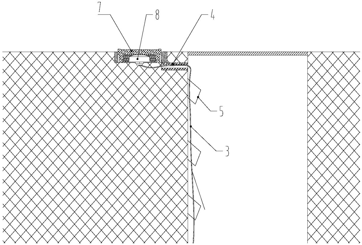
[0029] Such as figure 2 , the hidden antenna structure for underground communication includes a cable identification plate 7, a disc antenna 8 and an antenna extension 3. The cable identification plate is made of SMC material, which is fully insulated, corrosion-resistant, high in mechanical strength, has no recycling value, and is environmentally friendly and safe; The sign is fixed to the ground surface by concrete. The disc antenna is set in the cable identification plate and fixed by glue filling. The cable identification plate is not only eye-catching, but also can play a role in warning and marking the direction of the cable, and the disc antenna is protected from the sun. Rain and aging ensure the stability of signal transmission. One end of the antenna extension line is connected to the disc antenna, and the other end is connected to the underground equipment. A PVC hard pipe 4 is embedded in the soil layer where the antenna extension line passes. After the antenna ...


PUM


Abstract

The invention discloses a hidden antenna structure for underground communication. The hidden antenna structure comprises a cable identifier,a ground surface antenna and an antenna extension line,and the cable identifier is installed on the ground surface close to a cable tunnel or a wellhead of a joint well; the ground surface antenna is arranged in the cable identifier,one end of the antenna extension line is connected with the ground surface antenna,and the other end of the antenna extension line is connected with an underground device. According to the hidden antenna structure for underground communication,wireless signals can be normally received through the ground surface antenna on the ground,so that wireless communication between a tunnel and equipment in the joint well is achieved,and the situation that signals of wireless transmission in the tunnel and the joint well are not good and accordingly data transmission cannot be achieved is eliminated. Meanwhile,the cable identifiercan protect and shield the ground surface antenna,the ground surface antenna can be prevented from being damaged,and normal and stable operation of the earth surface antenna is guaranteed.

Description

technical field [0001] The invention relates to the technical field of wireless communication, in particular to a hidden antenna structure for underground communication. Background technique [0002] With the development of wireless communication technology, mobile communication products have become the mainstream of scientific and technological products at this stage. Through GPRS, 4G, WIFI and other wireless communication technologies to achieve information exchange between products, the products have achieved the functions of mutual contact and resource sharing, similar to Since such mobile communication products are more and more used in the power industry, antennas are indispensable for the communication of the above mobile products. [0003] However, due to obstacles such as soil, concrete, steel mesh, and manhole covers, there is usually no good wireless network coverage in power tunnels and joint shafts, so wireless communication products used in power tunnels are us...

Claims


Application Information

Patent Timeline
Patent Type & Authority Applications(China)
IPC IPC(8): H01Q1/36H01Q1/22H01Q1/12
CPCH01Q1/1207H01Q1/22H01Q1/36
Inventor 李旭刘兵辉廖家威欧君兰
Owner CHANGLAN CABLE ACCESSORIES
Why Eureka
Try Eureka