
Mixed excitation flux switching motor having stator with claw pole bypass structure

A magnetic flux switching motor and hybrid excitation technology, applied in synchronous machines, electrical components, electromechanical devices, etc., can solve problems such as adverse effects on motor performance, improve independent design margins, save materials, and eliminate coil ends. Effect

Active Publication Date: 2018-10-12
CHINA UNIV OF PETROLEUM (EAST CHINA)
View PDF5 Cites 2 Cited by
  • Summary
  • Abstract
  • Description
  • Claims
  • Application Information

AI Technical Summary

Problems solved by technology

[0005] Technical problem: In order to solve the defects of the traditional hybrid excitation flux switching motor due to the adverse effect of the placement position of the excitation winding on the performance of the motor, the present invention provides a hybrid excitation flux switching motor with a claw pole bypass structure in the stator

Method used


Image

  • Mixed excitation flux switching motor having stator with claw pole bypass structure
  • Mixed excitation flux switching motor having stator with claw pole bypass structure
  • Mixed excitation flux switching motor having stator with claw pole bypass structure

Examples


Embodiment 1

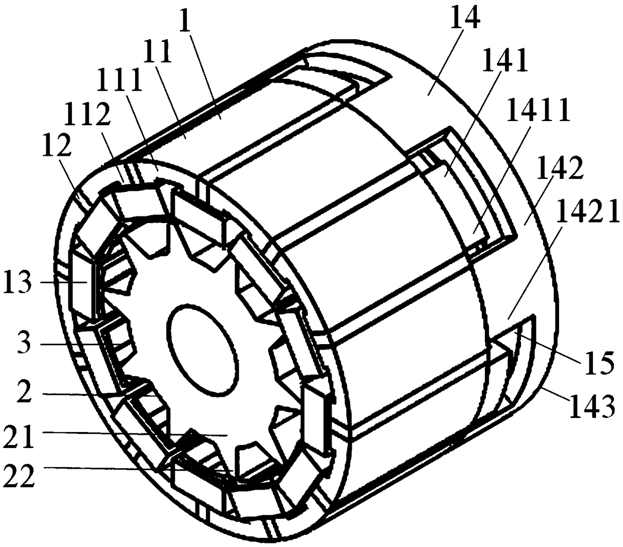
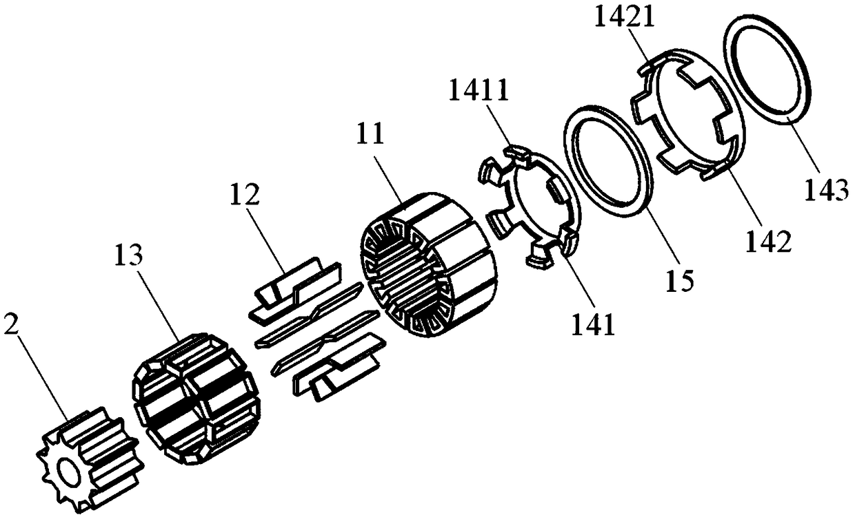
[0043] Such as figure 1 , 2 , 3, 4, 5, and 6.

[0044] A hybrid excitation flux switching motor with a claw pole bypass structure on the stator, comprising a stator 1 with a claw pole bypass structure, a rotor 2 with salient poles coaxially arranged in the stator 1, the An air gap 3 is provided between the stator 1 and the rotor 2;

[0045] The stator 1 is composed of a number of U-shaped stator cores 11 arranged at equal intervals along the circumference with the opening direction radially facing the center of the circle, permanent magnets 12 embedded between adjacent U-shaped stator core teeth 112, and wound in the form of concentrated winding. The armature winding 13 on the adjacent U-shaped stator core teeth 112, the claw pole bypass assembly 14 and the excitation coil 15 are formed. Among them, the U-shaped stator core 11 is composed of a stator core yoke 111 and a stator core tooth 112; the permanent magnet 12 is magnetized tangentially along the circumference, and th...

Embodiment 2

[0050] Such as figure 1 , 2 shown

[0051] A hybrid excitation flux switching motor with a claw pole bypass structure in the stator as described in Embodiment 1, the difference is that the claw pole bypass assembly 14 consists of separated U-shaped stator cores with the same magnetic pole polarity The yoke 111 extends from one side of the axial direction to an axial primary pole core ring 141 with an axial Z-shaped claw pole 1411, and a separate U-shaped stator core yoke 111 with the same magnetic pole polarity is aligned in the axial direction. An axial-type secondary pole core ring 142 with axial straight-toothed claw poles 1421 extends from the side, and is arranged on the same axial side of the primary pole core ring 141 and the secondary pole core ring 142 to connect them together in the radial direction. Consists of a radial cover core ring 143;

[0052] The axial lengths of the primary pole core ring 141 and the secondary pole core ring 142 are equal;

[0053] The r...

Embodiment 3

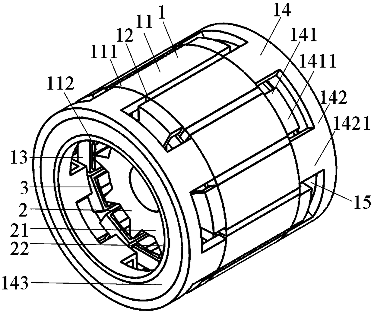
[0057] Such as image 3 , 4 shown

[0058] As described in Embodiment 2, a hybrid excitation flux switching motor with a claw pole bypass structure in the stator, the difference is that it can also be designed to set the claw pole bypasses on both sides of the U-shaped stator core yoke 111 axially. The bilateral bypass excitation structure of the road assembly 14, the structure of the claw pole bypass assembly 14 on each side is the same as that described in Embodiment 2;

[0059] The claw poles of the primary pole core ring 141 of the claw pole bypass assembly 14 on both sides are respectively connected to U-shaped stator core yokes 111 with different magnetic pole polarities along the axial direction in space, that is to say, the claw poles on one side are The axial Z-shaped claw poles 1411 of the primary pole core ring 141 of the road assembly 14 are respectively connected with the axial Z-shaped claw poles 1411 of the primary pole core ring 141 of the claw pole bypass as...


PUM


Abstract

The invention discloses a mixed excitation flux switching motor having a stator with a claw pole bypass structure. The stator, a rotor and an air gap which are coaxially arranged are arranged on a motor; the stator is composed of a plurality of U-shaped stator iron cores equidistantly arranged at intervals along the circumference, a permanent magnet embedded between the adjacent U-shaped stator iron core teeth, an armature winding wound on the adjacent U-shaped stator iron core teeth, a claw pole bypass component and an excitation coil; the claw pole bypass component is composed of a primary iron core ring connected with U-shaped stator iron core magnet yokes with different magnetic polarities through the claw pole, a secondary iron core ring and a shielding iron core ring for connecting the primary iron core ring and the secondary iron core, the primary iron core ring, the secondary iron core and the shielding iron core ring form an annular cavity structure in a surrounding way; the excitation coil is placed in the annular cavity; and the rotor is composed of a rotor iron core and a rotor salient pole. The flux switching motor main body structure cannot be changed, the motor has reliable structure and can conveniently regulate the air gap magnetic field by placing the excitation coil through the claw pole bypass structure, and is suitable for the wide-speed regulation application occasion.

Description

technical field [0001] The invention relates to a hybrid excitation magnetic flux switching motor, in particular to a hybrid excitation magnetic flux switching motor with a claw pole bypass structure on the stator in the axial or radial direction. Background technique [0002] Flux switching permanent magnet motor is a new type of stator permanent magnet doubly salient pole motor. Compared with the traditional rotor permanent magnet motor, the stator of the flux switching permanent magnet motor is equipped with permanent magnets and concentrated armature windings, and the rotor structure is extremely simple. Due to the special winding complementary structure, the motor has highly sinusoidal permanent magnet flux linkage and no-load induced electromotive force, high torque output capacity and power density. [0003] However, due to the strong magnetic field characteristics of permanent magnet materials, the air gap magnetic field in permanent magnet motors remains basically ...

Claims


Application Information

Patent Timeline
Patent Type & Authority Applications(China)
IPC IPC(8): H02K21/38H02K21/04
CPCH02K21/04H02K21/38
Inventor 李祥林于世洋申发文王玉彬
Owner CHINA UNIV OF PETROLEUM (EAST CHINA)
Learn More