Lifting type stirring structure used in sewage treatment tank

A sewage treatment tank, lift-type technology, applied in mixer accessories, mixers with rotary mixing devices, chemical/physical processes, etc., can solve problems such as applicability and practicality limitations, affecting the effect of mixing, and inability to move vertically. , to achieve the effect of strong practicability, improved effect and good use stability

Active Publication Date: 2018-10-16
杭州西斗环境科技有限公司
View PDF4 Cites 5 Cited by
  • Summary
  • Abstract
  • Description
  • Claims
  • Application Information

AI Technical Summary

Problems solved by technology

[0002] The sewage treatment tank is an indispensable part of the sewage treatment system. It mainly includes a filter tank, a sedimentation tank, a mixing tank, a reaction tank and a clean water tank. The mixing tank in the prior art is mainly composed of a tank body, a bracket and The agitator is composed of agitator, which uses the rotation of the agitator blade to stir the sewage treatment tank. However, the agitator in the agitation tank can only rotate horizontally and cannot move vertically, and stratification is easy to occur in the sewage tank, which makes the agitation effect extremely At the same time, because the blades of the agitator are prone to fouling when used for a long time, which affects the stirring effect, the applicability and practicability are limited

Method used


Image

  • Lifting type stirring structure used in sewage treatment tank
  • Lifting type stirring structure used in sewage treatment tank

Examples


Embodiment 1

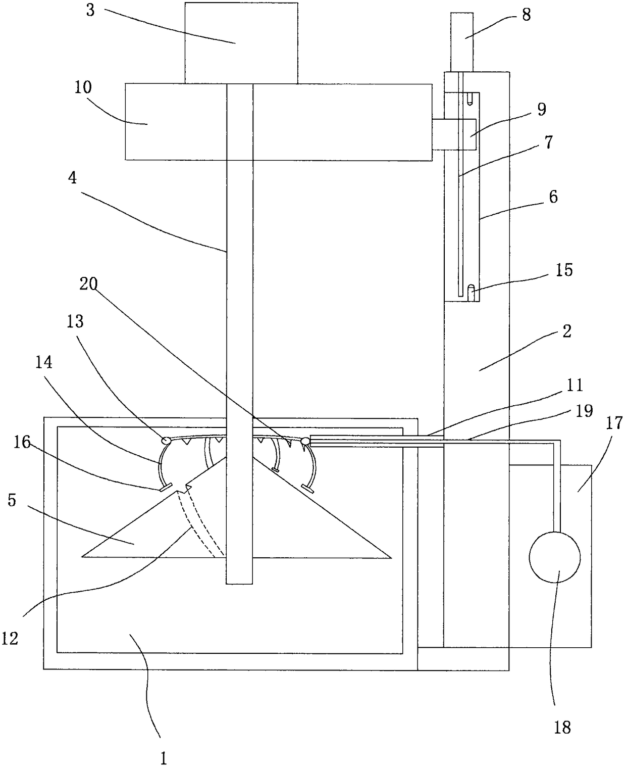
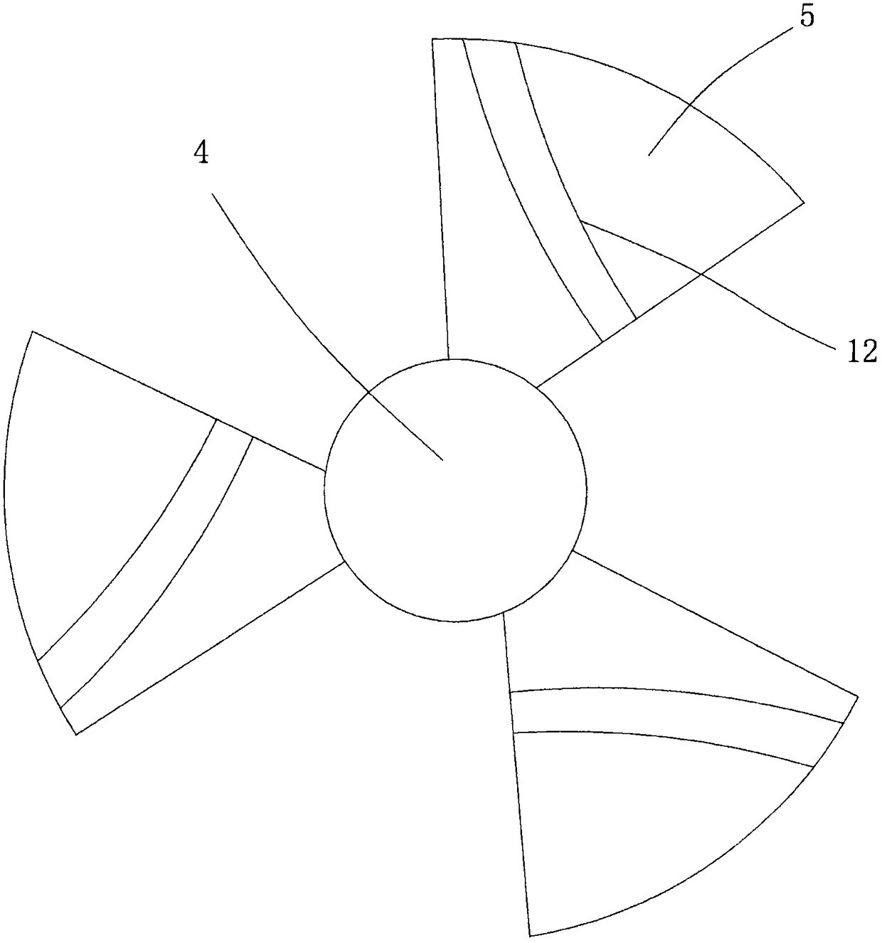
[0015] figure 1 with figure 2 A specific embodiment of the present invention is shown, wherein figure 1 Is a schematic diagram of the structure of the present invention; figure 2 It is the specific structure of the stirring blade in the present invention.

[0016] see figure 1 with figure 2 , A lifting type stirring structure used in a sewage treatment tank, comprising a bracket 2 fixed on the stirring tank 1, a stirring motor 3 is arranged on the bracket 2, and a stirring motor 3 is arranged on the main shaft of the stirring motor 3 The shaft 4 is provided with a stirring blade 5 on the stirring shaft 4, a vertical slide groove 6 is provided on the support 2, and a transmission screw 7 is provided in the vertical slide groove 6; A drive motor 8 connected to the drive screw 7 is fixed on the top of the bracket 2, and a sliding block 9 is provided in the vertical sliding groove 6, and the sliding block 9 is threadedly connected to the drive screw 7 In the upper part, a stirr...


PUM


Abstract

The invention discloses a lifting type stirring structure used in a sewage treatment tank. The lifting type stirring structure comprises a bracket fixed on a stirring tank; a stirring motor is arranged on the bracket; a stirring shaft rod is arranged on a main shaft of the stirring motor; stirring blades are arranged on the stirring shaft rod; a vertical sliding groove is formed in the bracket; adriving screw rod is arranged inside the vertical sliding groove; a driving motor connected with the driving screw rod is fixed at the top of the bracket; a sliding block is arranged inside the vertical sliding groove; a stirring seat is fixed on the sliding block; a descaling strut is arranged at the middle part of the bracket; spiral stirring water guiding grooves are formed in the surface of right triangles; a circular ring is arranged on the descaling strut; and curved elastic pieces are uniformly fixed on the bottom surface of the circular ring. The lifting type stirring structure provided by the invention is reasonable in structure, and has the advantages that the stirring effect is improved and the stratification is avoided; the descaling operation on the surface of the stirring blades is completed at the same time of lifting, so that the guarantee of the stability and reliability of stirring is facilitated; and the lifting type stirring structure is good in stability and strongin practicality.

Description

Technical field [0001] The invention belongs to the technical field of sewage treatment, and in particular relates to a lifting type stirring structure used in a sewage treatment tank. Background technique [0002] The sewage treatment tank is an indispensable part of the sewage treatment system. It mainly includes a filter tank, a sedimentation tank, a mixing tank, a reaction tank, and a clean water tank. The prior art mixing tank is mainly composed of a tank body, a support and The mixer is composed of agitator, which uses the rotation of the mixer blade to stir the sewage treatment tank. However, the agitator in the mixing tank can only rotate horizontally and cannot move vertically, and the sewage tank is prone to stratification, which makes the mixing effect very effective. At the same time, when the blades of the agitator are used for a long time, fouling is easy to occur, which affects the effect of mixing, and the applicability and practicability are limited. Summary of ...

Claims


Application Information

Patent Timeline
Patent Type & Authority Applications(China)
IPC IPC(8): B01F7/18B01F15/00
CPCB01F27/2312B01F35/123B01F27/90B01F2101/305
Inventor 南施西
Owner 杭州西斗环境科技有限公司
Why Eureka
Try Eureka