Powder falling device of 3D printer

A 3D printer and powder drop technology, applied in the field of 3D printing, can solve problems such as quality defects, powder waste, and difficulty in quantification.

Inactive Publication Date: 2018-10-16
安徽中健三维科技有限公司
View PDF8 Cites 5 Cited by
  • Summary
  • Abstract
  • Description
  • Claims
  • Application Information

AI Technical Summary

Problems solved by technology

[0003] The metal powder raw material is stored in the powder box, and the powder raw material is passed into the powder spreading device during use. The conventional powder spreading system is either located under the forming platform, and the powder in the powder cylinder is pushed to the forming platform through the piston: or located on the forming platform In the upper part, the powder falling method uses the gravity of the powder itself to make the powder fall into the powder spreading device. There is a problem that it is difficult to quantify the powder falling method, and the deviation of the powder supply will affect the quality of the powder spreading or the waste of the powder, and the powder In the daily storage, the raw materials are bonded after contact with the water vapor in the air, which leads to the quality of the powder sintering and forming is prone to defects. The present invention designs a special powder falling device for the above problems.

Method used


Image

  • Powder falling device of 3D printer
  • Powder falling device of 3D printer
  • Powder falling device of 3D printer

Examples


Embodiment Construction

[0014] Preferred embodiments of the present invention will be described in detail below in conjunction with the accompanying drawings.

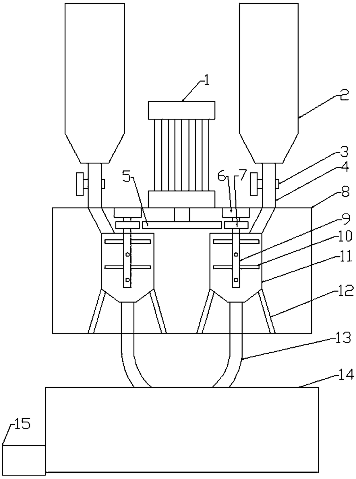
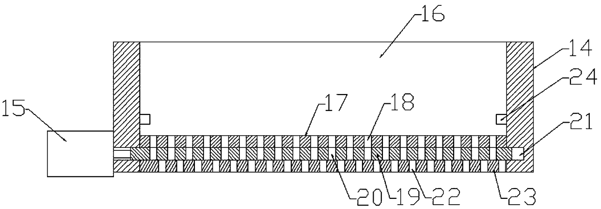
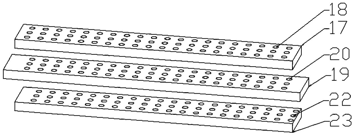
[0015] Figure 1-3 The specific embodiment of the present invention is shown: a powder dropping device of a 3D printer, comprising a stirring box 8 and a powder dropping box 14, the upper end of the stirring box 8 is provided with a servo motor 1, and the main shaft of the servo motor 1 is located in the stirring box 8 inside and the upper end of the main shaft is provided with a large gear 5, the two ends of the servo motor 1 are provided with a feed pipe 4 and extend to the inside of the mixing box 8, the feed pipe 4 is provided with a solenoid valve 3, and the feed pipe 4 The upper end of 4 is provided with a steel cylinder 2, the inner lower end of the stirring box 8 is provided with a leg 12, the upper end of the leg 12 is fixed with a stirring tank 11, the feeding pipe 4 communicates with the upper end of the stirring tank 11, and the i...


PUM


Abstract

The invention discloses a powder falling device of a 3D printer. The device comprises stirring box and a powder falling box, wherein a servo motor is arranged at the upper end of the stirring box, a large gear is arranged at the upper end of a main shaft of the servo motor, feeding pipes are arranged at the two ends of the servo motor, and an electromagnetic valve is arranged on the feeding pipes;steel cylinders are arranged at the upper ends of the feeding pipes, supporting legs are arranged at the lower end inside the stirring box, a stirring tank is fixed at the upper end of the supportinglegs, a rotating shaft fixing base is arranged at the upper end of the interior of the stirring box, and the rotating shaft is arranged in the rotating shaft fixing base; a small gear is arranged onthe rotating shaft, a material falling pipe is connected to the lower end of a stirring pipe, a powder storage cavity is formed in the upper end of the interior of the powder falling box, and a powderinlet plate is fixed at the bottom of the powder storage cavity; a plurality of powder inlet holes are formed in the powder inlet plate in a array mode, a rectangular groove is formed in the lower end of the powder inlet plate, and a powder storage plate is arranged in the rectangular groove; and a plurality of powder storage holes are formed in the powder storage plate, a powder falling plate isfixed at the lower end of the powder storage plate, and a plurality of powder falling holes are formed in the powder falling plate. The powder falling device realizes a pre-dispersion treatment of the powder and the powder quantitative falling, the probability of flaws caused by pasting is reduced, and the powder utilization rate is improved.

Description

technical field [0001] The invention relates to the field of 3D printing, in particular to a powder dropping device of a 3D printer. Background technique [0002] The metal powder rapid prototyping printer can make a section with a certain micro-thickness and a specific shape each time according to the shape of the part, and then bond the sections of each layer layer by layer to obtain the three-dimensional part that needs to be manufactured. Metal powder Because rapid prototyping printers can directly manufacture solid parts from computer 3D design data without any hard molds, they have been widely used in many fields such as machinery and medical treatment. [0003] The metal powder raw material is stored in the powder box, and the powder raw material is passed into the powder spreading device during use. The conventional powder spreading system is either located under the forming platform, and the powder in the powder cylinder is pushed to the forming platform through the...

Claims


Application Information

Patent Timeline
IPC IPC(8): B22F3/00B33Y30/00B22F12/50B22F12/52
CPCB22F3/005B33Y30/00B22F10/00B22F10/10B22F12/222B22F12/50Y02P10/25
Inventor 张存柱
Owner 安徽中健三维科技有限公司
Why Eureka
Try Eureka