Air pressure diaphragm spring chuck spindle

A diaphragm spring and spindle technology, applied in the field of the pneumatic diaphragm spring chuck spindle, can solve the problems of the dimensional consistency and geometric accuracy of the processed workpiece, affecting the machining accuracy and production efficiency, and short service life, so as to solve the problem of the shaft head Consistency problem, reducing the single running-in link, reducing the effect of workpiece instability

Pending Publication Date: 2018-10-16
宁波锋行自动化科技有限公司
View PDF0 Cites 2 Cited by
  • Summary
  • Abstract
  • Description
  • Claims
  • Application Information

AI Technical Summary

Problems solved by technology

If the spring collet is used for a long time, if the wear exceeds a certain limit, the workpiece will not be firmly clamped, which will directly affect the machining accuracy and production efficiency. At this time, the spring collet will be scrapped, which will increase the manufacturing cost of the fixture and improve the wear resistance. The hardness of the collet must be increased, but the elasticity of the collet is weakened if the hardness is too high, and the service life is short
[0004] For the chuck, the clamping force is the key, which is the force exerted by the machine tool on the workpiece through the chuck. The spring chuck of the existing product is tightened by connecting the outer screw of the pull rod with the inner thread of the rear end of the spring chuck. Axial tension is generated, and then the axial tension is converted into a clamping force perpendicular to the center of the spring chuck by the conical surface called the locking angle at the front end of the machine tool spindle. The spring chuck must be kept in contact with the workpiece (or tool) The positioning reference is the same as the spindle, the relative movement between the collet and the workpiece (or tool) will cause incorrect part processing, and the relative rotation or relative axial movement between the collet and the workpiece (or tool) will cause machining Workpiece dimensional consistency and geometric accuracy suffer

Method used


Image

  • Air pressure diaphragm spring chuck spindle

Examples


Embodiment Construction

[0017] The following are specific embodiments of the present invention and in conjunction with the accompanying drawings, the technical solutions of the present invention are further described, but the present invention is not limited to these embodiments.

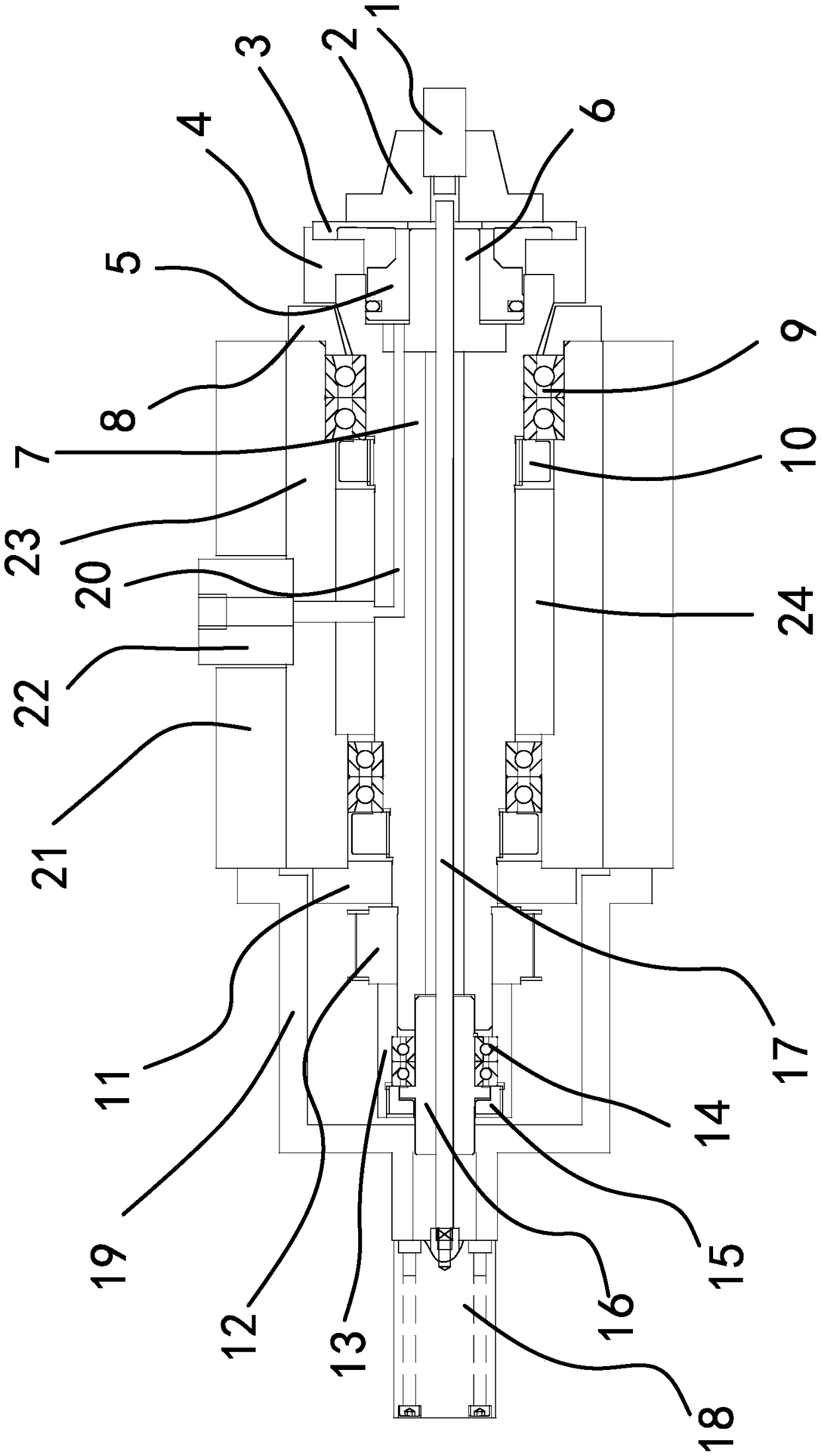
[0018] Such as figure 1 As shown, the air pressure diaphragm collet main shaft includes a shaft fixing seat 21, an air inlet joint seat 22 is installed on the shaft fixing seat 21, a bearing seat 23 is arranged in the shaft fixing seat 21, and a bearing seat 23 is worn in the bearing seat 23. The main shaft 7 is provided with an air inlet sleeve 24 between the main shaft 7 and the bearing seat 23, the head end of the main shaft 7 is provided with a support column 6, and a piston 5 is arranged between the support column 6 and the main shaft 7, and the piston 5 is connected to the air inlet joint The seats 22 are communicated through the air intake channel 20, a diaphragm spring seat 4 is provided at the head end of the main...


PUM


Abstract

The invention provides an air pressure diaphragm spring chuck spindle, and belongs to the technical field of machines. The air pressure diaphragm spring chuck spindle comprises a shaft fixing seat, and an air inlet connector seat is mounted on the shaft fixing seat. A bearing pedestal is arranged in the shaft fixing seat. A spindle body penetrates the bearing pedestal, and an air inlet sleeve is arranged between the spindle body and the bearing pedestal. A supporting column is arranged at the head end of the spindle body, and a piston is arranged between the supporting column and the spindle body. The piston communicates with the air inlet connector seat through an air inlet channel, and a diaphragm spring seat is arranged at the head end of the spindle body, a diaphragm spring is arrangedon the diaphragm spring seat, and a chuck for clamping a workpiece is arranged on the outer side of the diaphragm spring. When air enters the air inlet channel, the diaphragm spring can deforms through the piston, and the chuck is in a clamping state. A driving wheel capable of driving the spindle body to rotate is arranged at the rear end of the spindle body. The air pressure diaphragm spring chuck spindle has the beneficial effects of being simple in structure and good in clamping effect.

Description

technical field [0001] The invention belongs to the technical field of machinery, and in particular relates to a main shaft of an air pressure diaphragm collet. Background technique [0002] The collet chuck spindle is matched with precision CNC lathes, precision grinding machines or various special machinery for precision machining. It is used in the clamping and processing of thin ring workpieces, thin tube workpieces or various fragile workpieces to ensure that the workpiece is not clamped. Damaged or deformed, it has been successfully applied to the clamping processing of precision mechanical parts, precision electronic parts, optical parts, military parts, medical parts and other precision parts. [0003] At this stage, the market is mainly manifested as a single-product spring collet, which is installed on a drilling / milling machine, and its function is to clamp a drill or a milling cutter. If the spring collet is used for a long time, if the wear exceeds a certain li...

Claims


Application Information

Patent Timeline
Patent Type & Authority Applications(China)
IPC IPC(8): B23B31/16B24B41/06
CPCB23B31/16287B24B41/062
Inventor 戴积峰
Owner 宁波锋行自动化科技有限公司
Why Eureka
Try Eureka