
Straw pulverizer

The technology of a straw grinder and crushing device, which is applied in the field of machinery, can solve the problems of poor crushing and cutting effects of the straw grinder, and achieve the effect of improving the crushing effect, improving efficiency, and good effect

Pending Publication Date: 2021-05-07
焦超锦
View PDF0 Cites 0 Cited by
  • Summary
  • Abstract
  • Description
  • Claims
  • Application Information

AI Technical Summary

Problems solved by technology

[0005] Aiming at the deficiencies of the prior art, the present invention provides a straw grinder, which solves the problem of poor crushing and cutting effect inside the straw grinder

Method used


Image

  • Straw pulverizer
  • Straw pulverizer
  • Straw pulverizer

Examples


Embodiment 1

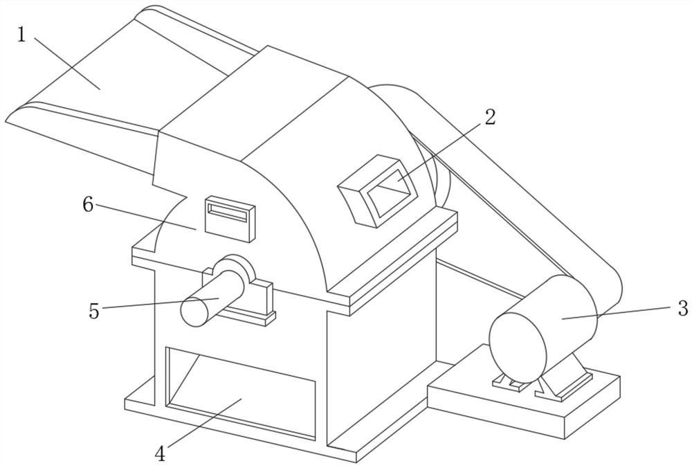
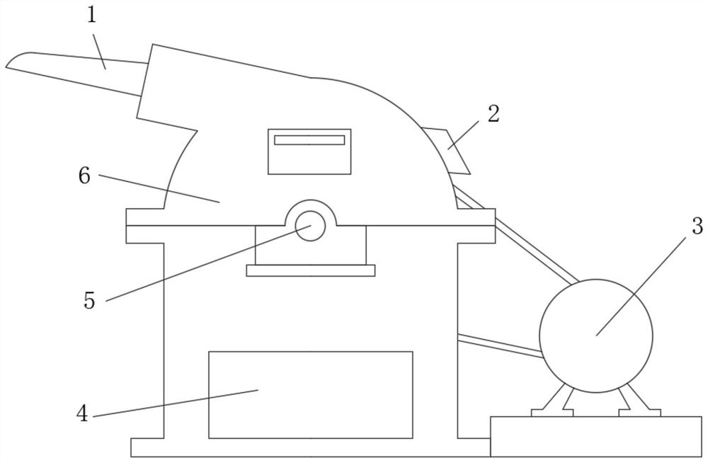
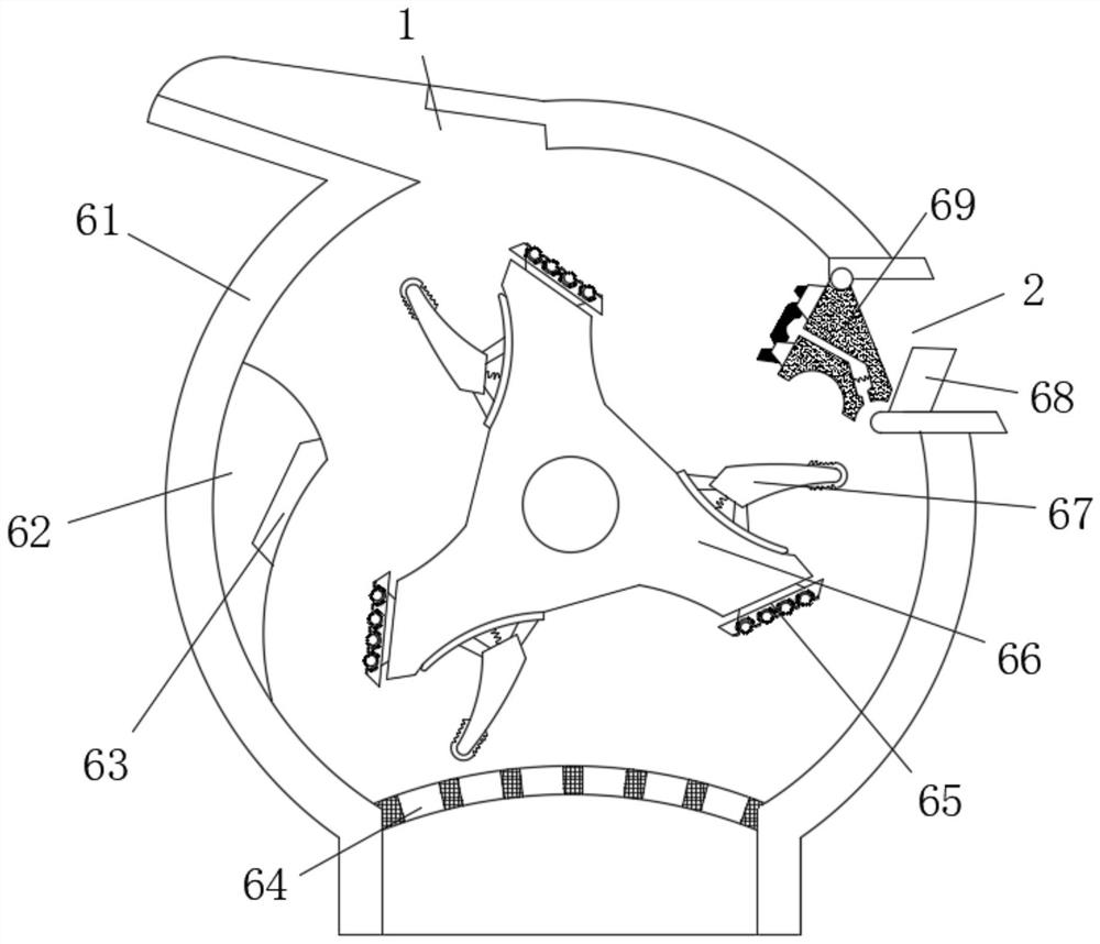
[0032] Such as Figure 1-5As shown, the present invention provides a technical solution: a straw grinder, including a crushing device 6, a first rotating shaft 5 is sleeved in the middle of the front of the crushing device 6, and the outer surface of the first rotating shaft 5 is connected by transmission. There is a rotating motor 3, the bottom of the front of the crushing device 6 is provided with a discharge port 4, the left side of the top of the crushing device 6 is provided with a feed inlet 1, and the right side of the top of the crushing device 6 is provided with a debris outlet 2. The crushing device 6 includes a casing 61, the top of the casing 61 is fixedly connected to the opening end of the feed inlet 1, and the right side of the casing 61 is fixedly connected to the left side of the debris outlet 2, and the debris The opening on the left side of the outlet 2 is rotatably connected with a crushing device 69, and the bottom of the inner cavity of the debris outlet ...

Embodiment 2

[0039] Such as Figure 6-7 As shown, on the basis of Embodiment 1, the present invention provides a technical solution: the crushing device 69 includes a discharge pipe 692 and a rotating block 694, and the outer surface of the discharge pipe 692 is fixedly connected to the casing 61 The bottom of the inner cavity of the discharge pipe 692 is fixedly connected to the bottom end of the limit plate 68, the top of the inner cavity of the discharge pipe 692 is fixedly connected with the second rotating shaft 691, and the discharge pipe 692 passes through the first The two rotating shafts 691 are rotatably connected to the top of the rotating block 694. The inside of the rotating block 694 is provided with a through hole 697. The surfaces on both sides of the inner wall of the through hole 697 are fixedly connected by the second spring 693. The left side of the rotating block 694 A backing plate 695 is fixedly connected to the side, and a grinding device 696 is fixedly connected to...


PUM


Abstract

The invention discloses a straw pulverizer, and relates to the technical field of machines. The straw pulverizer comprises a pulverizing device, a first rotating shaft sleeves the middle of the front face of the pulverizing device, the outer surface of the first rotating shaft is in transmission connection with a rotating motor, a discharge hole is formed in the bottom of the front face of the pulverizing device, and a feeding hole is formed in the left side of the top of the pulverizing device. A scrap outlet is formed in the right side of the top of the pulverizing device, the pulverizing device comprises a machine shell, the top of the machine shell is fixedly connected to the opening end of the feeding hole, the right side of the machine shell is fixedly connected to the left side of the scrap outlet, and a crushing device is rotationally connected to an opening in the left side of the scrap outlet. According to the straw pulverizer, straw enters the straw pulverizing device from the feeding hole, when the rotating motor is started to enable a stirring rotating wheel to rotate clockwise, a pulverizing and cutting device can be matched with a cutting plate to cut and pulverize the straw, and the straw cutting effect is achieved.

Description

technical field [0001] The invention relates to the technical field of machinery, in particular to a straw grinder. Background technique [0002] The straw grinder can crush corn stalks, straw, peanut skins, bean stalks, firewood and other combustible crop waste stalks. The useless burning of these crop stalks is avoided, the environment is well protected, and renewable energy is effectively developed. The machine has reliable performance, simple and convenient operation. The equipment produces a wide range of raw materials, and can be adapted to combustible crop waste stalks such as corn stalks, straws, peanut skins, bean stalks, and firewood. The straw shredder is mainly used for shredding processing of plant straws such as crop straws and branch diameters below 5CM, and can also be used for shredding processing of various crop straws and pastures. [0003] In the use of the existing agricultural straw grinder, it is found that the dust generated during the crushing and...

Claims


Application Information

Patent Timeline
Patent Type & Authority Applications(China)
IPC IPC(8): A01F29/02A01F29/00A01F29/14A01F29/09
CPCA01F29/005A01F29/02A01F29/09A01F29/095A01F29/14
Inventor 焦超锦
Owner 焦超锦
Learn More