Straw and forage cutting device for animal husbandry

A cutting device and forage technology, which is applied to cutting equipment, mixers with rotating stirring devices, applications, etc., can solve the problems of straw fatigue, low work efficiency, time-consuming and laborious, etc.

Inactive Publication Date: 2021-07-23
惠安极地星空科技有限公司
View PDF7 Cites 0 Cited by
  • Summary
  • Abstract
  • Description
  • Claims
  • Application Information

AI Technical Summary

Problems solved by technology

[0004] In order to overcome the disadvantages that manual cutting of straw is easy to hurt hands, it is time-consuming and laborious, and cutting straw for a long time will cause fatigue and low work efficiency. device

Method used


Image

  • Straw and forage cutting device for animal husbandry
  • Straw and forage cutting device for animal husbandry
  • Straw and forage cutting device for animal husbandry

Examples


Embodiment 1

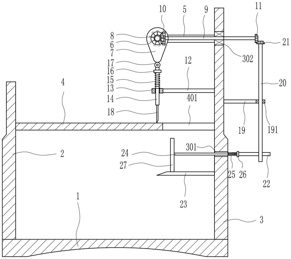
[0024] A straw forage cutting device for animal husbandry, such as Figure 1-5As shown, it includes a base 1, a first bracket 2, a second bracket 3, a first bearing 302, a first transverse support plate 4, a mounting plate 5, a motor 6, a first cam 7, a first bevel gear 8, a first Shaft 9, second bevel gear 10, third bevel gear 11, cross strut 12, sliding sleeve 13, slide rod 14, first spring 15, stopper 16, roller 17, cutting knife 18, second cross strut 19. The second bearing 191, the second shaft 20, the fourth bevel gear 21, the second cam 22, the blanking plate 23, the first push rod 24, the second spring 25, the top plate 26 and the first push plate 27, the base 1. The first bracket 2 is fixedly connected to the upper left, and the second bracket 3 is fixedly connected to the upper right of the base 1. The lower part of the second bracket 3 has a first through hole 301, and the upper part of the second bracket 3 is embedded with a first bearing 302. A first transverse s...

Embodiment 2

[0026] A straw forage cutting device for animal husbandry, such as Figure 1-5 As shown, it includes a base 1, a first bracket 2, a second bracket 3, a first bearing 302, a first transverse support plate 4, a mounting plate 5, a motor 6, a first cam 7, a first bevel gear 8, a first Shaft 9, second bevel gear 10, third bevel gear 11, cross strut 12, sliding sleeve 13, slide rod 14, first spring 15, stopper 16, roller 17, cutting knife 18, second cross strut 19. The second bearing 191, the second shaft 20, the fourth bevel gear 21, the second cam 22, the blanking plate 23, the first push rod 24, the second spring 25, the top plate 26 and the first push plate 27, the base 1. The first bracket 2 is fixedly connected to the upper left, and the second bracket 3 is fixedly connected to the upper right of the base 1. The lower part of the second bracket 3 has a first through hole 301, and the upper part of the second bracket 3 is embedded with a first bearing 302. A first transverse ...

Embodiment 3

[0029] A straw forage cutting device for animal husbandry, such as Figure 1-5 As shown, it includes a base 1, a first bracket 2, a second bracket 3, a first bearing 302, a first transverse support plate 4, a mounting plate 5, a motor 6, a first cam 7, a first bevel gear 8, a first Shaft 9, second bevel gear 10, third bevel gear 11, cross strut 12, sliding sleeve 13, slide rod 14, first spring 15, stopper 16, roller 17, cutting knife 18, second cross strut 19. The second bearing 191, the second shaft 20, the fourth bevel gear 21, the second cam 22, the blanking plate 23, the first push rod 24, the second spring 25, the top plate 26 and the first push plate 27, the base 1. The first bracket 2 is fixedly connected to the upper left, and the second bracket 3 is fixedly connected to the upper right of the base 1. The lower part of the second bracket 3 has a first through hole 301, and the upper part of the second bracket 3 is embedded with a first bearing 302. A first transverse ...


PUM


Abstract

The invention relates to a cutting device, in particular to a straw and forage cutting device for the animal husbandry. The straw and forage cutting device for the animal husbandry aims at achieving the technical purposes of manual auxiliary pushing, automatic cutting and automatic stirring. According to the technical scheme, the straw and forage cutting device for the animal husbandry comprises a base, a first support, a second support, a first bearing, a first transverse supporting plate, a mounting plate, a motor, a first cam, a first bevel gear, a first shaft rod and the like; and the first support is fixedly connected to the upper left of the base, the second support is fixedly connected to the upper right of the base, a first through hole is formed in the lower portion of the second support, and the first bearing is embedded in the upper portion of the second support. The straw and forage cutting device for the animal husbandry has the functions of manual auxiliary pushing, automatic cutting and automatic stirring and overcomes the defects that hands are easily hurt by manual straw cutting, time and labor are wasted, people feel tired when forage is cut for a long time and the working efficiency is low, and the straw and forage cutting device has the characteristics of being convenient to use, safe to use, easy to operate, low in manufacturing cost and the like.

Description

technical field [0001] The invention relates to a cutting device, in particular to a straw cutting device for animal husbandry. Background technique [0002] Straw, called stalks in ancient times, also known as grass straw, refers to the remaining stems and leaves of gramineous crops such as rice, wheat, and corn after threshing. Among them, rice straw is often called rice straw and rice straw, and wheat straw is called Straw, before industrialization, farmers used straw in a variety of ways, and it was very rich. For example, in southern China, people dried and stored rice straw, which can be used as firewood, weaving cushions, mattresses, brooms and other household items, and laying pads for livestock. , feeding livestock, composting and returning manure to the field, and even being used to make roofs for simple houses, etc., are rarely directly wasted. [0003] At present, when feeding livestock in large farms, manual cutting of straw is easy to hurt hands, not only time...

Claims


Application Information

Patent Timeline
Patent Type & Authority Applications(China)
IPC IPC(8): A01F29/08A01F29/09A23N17/00B01F7/02B01F7/04
CPCA01F29/08A01F29/095A23N17/00A23N17/007B01F27/62B01F27/70B01F2101/18
Inventor 李奕冲
Owner 惠安极地星空科技有限公司
Why Eureka
Try Eureka