Metal piece clamping device for metal cutting machine tool machining

A metal cutting and clamping device technology, which is applied in the direction of metal processing machinery parts, metal processing equipment, positioning devices, etc., can solve the problems of small size range of clamping metal parts, inconvenient adjustment of the angle of the clamping device, etc., to achieve improved clamping Range, ease of processing, and anti-slip effects

Inactive Publication Date: 2018-10-16
HUBEI HAILIAN TECH CONSULTATION CO LTD
View PDF0 Cites 35 Cited by
  • Summary
  • Abstract
  • Description
  • Claims
  • Application Information

AI Technical Summary

Problems solved by technology

[0003] During the processing of metal cutting machine tools, it is often necessary to use clamping devices to fix metal parts. Most of the existing clamping devices are inconvenient to adjust the angle, and the size range of clamping metal parts is small.

Method used


Image

  • Metal piece clamping device for metal cutting machine tool machining
  • Metal piece clamping device for metal cutting machine tool machining
  • Metal piece clamping device for metal cutting machine tool machining

Examples


Embodiment Construction

[0021] The following will clearly and completely describe the technical solutions in the embodiments of the present invention with reference to the accompanying drawings in the embodiments of the present invention. Obviously, the described embodiments are only some, not all, embodiments of the present invention.

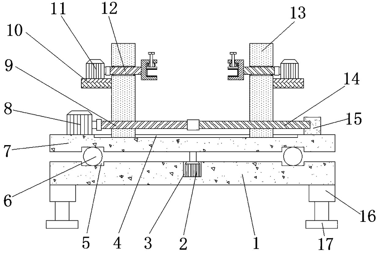
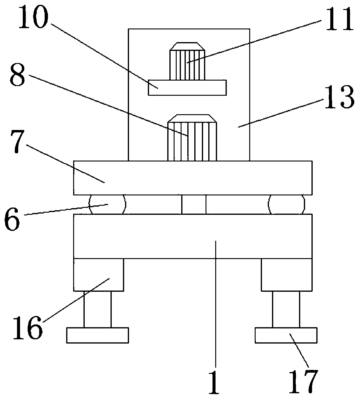
[0022] refer to Figure 1-3 , a metal piece clamping device for metal cutting machine tool processing, including a base 1 and a turntable 7, the dead corners of the bottom outer wall of the base 1 are fixed with hydraulic cylinders 16 by screws, and the outer walls of the four hydraulic cylinders 16 away from the base 1 are all The legs 17 are fixed by screws, and the central axis of the top outer wall of the base 1 is provided with an installation groove, and the bottom inner wall of the installation groove is fixed with a first servo motor 2 by screws, and the output shaft of the first servo motor 2 is connected to the turntable 7 by screws. The outer wall of the b...


PUM


Abstract

The invention discloses a metal piece clamping device for metal cutting machine tool machining. A base and a rotating table are included, and the dead corners of the bottom outer wall of the base areeach fixedly provided with a hydraulic cylinder through a screw; the outer walls of the sides, away from the base, of the four hydraulic cylinders are each fixedly provided with a supporting leg through a screw; the center axis position of the top outer wall of the base is provided with an installing groove; the inner wall of the bottom of the installing groove is fixedly provided with a first servo motor through a screw; an output shaft of the first servo motor is fixed to the center axis position of the bottom outer wall of the rotating table through a screw; the outer walls of the oppositesides of the base and the rotating table are each provided with an annular groove; and the inner walls of the two annular grooves are connected with same rolling balls in an equal-distance uniform rolling manner. According to the metal piece clamping device for metal cutting machine tool machining, the height and the angle of the device can be adjusted, so that the device conveniently clamp metalpieces, and the distance between two adjusting blocks can be adjusted according to the size of the metal pieces so that the device can be used for clamping the metal pieces in different sizes.

Description

technical field [0001] The invention relates to the technical field of machine tool fixtures, in particular to a metal piece clamping device for metal cutting machine tool processing. Background technique [0002] Machine tools in a narrow sense usually only refer to metal cutting machine tools. Metal cutting machine tools are machines that use cutting methods to process metal blanks into machine parts. It is a machine that manufactures machines, so it is also called "working machine" or "tool machine", and is customarily referred to as a machine tool. The process of metal cutting is a process in which the tool and the workpiece move and interact with each other. The relative movement between the tool and the workpiece can be decomposed into two aspects, one is the main movement and the other is the feed movement. The most important movement that makes the workpiece and the tool move relative to each other and cut is called the main movement. The main motion speed of the ...

Claims


Application Information

Patent Timeline
Patent Type & Authority Applications(China)
IPC IPC(8): B23Q3/06B23Q1/25
CPCB23Q3/06B23Q1/25
Inventor 徐祖建苏平邓文军
Owner HUBEI HAILIAN TECH CONSULTATION CO LTD
Why Eureka
Try Eureka