
Automatic numerical control machining equipment applied to guide wheel production

A kind of processing equipment and automatic technology, which is applied in the direction of metal processing equipment, metal processing, manufacturing tools, etc., can solve the problems that production enterprises cannot expand large-scale production, cannot further improve productivity, and cannot realize fully automatic processing, so as to reduce processing time , Reduce labor intensity, improve the effect of automation

Inactive Publication Date: 2018-10-16
中山市誉胜智能科技有限公司
View PDF8 Cites 0 Cited by
  • Summary
  • Abstract
  • Description
  • Claims
  • Application Information

AI Technical Summary

Problems solved by technology

[0004] The solution of this application is that when the above-mentioned existing guide wheel CNC machining equipment cuts the arc position on the circumference of the guide wheel, fully automatic processing cannot be realized, and the workpiece still needs to be manually loaded and unloaded, which not only makes the operator labor intensive, but also It is impossible to further improve productivity, and at the same time, the production enterprise cannot expand large-scale production to meet the technical problems of more market demand. An automatic numerical control processing equipment applied to the production of guide wheels is provided.

Method used


Image

  • Automatic numerical control machining equipment applied to guide wheel production
  • Automatic numerical control machining equipment applied to guide wheel production
  • Automatic numerical control machining equipment applied to guide wheel production

Examples


Embodiment Construction

[0058] The present application will be described in further detail below through specific embodiments in conjunction with the accompanying drawings.

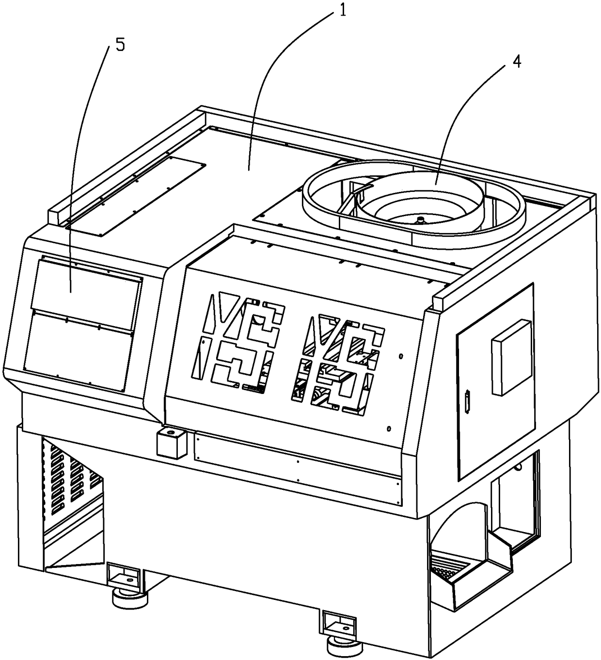
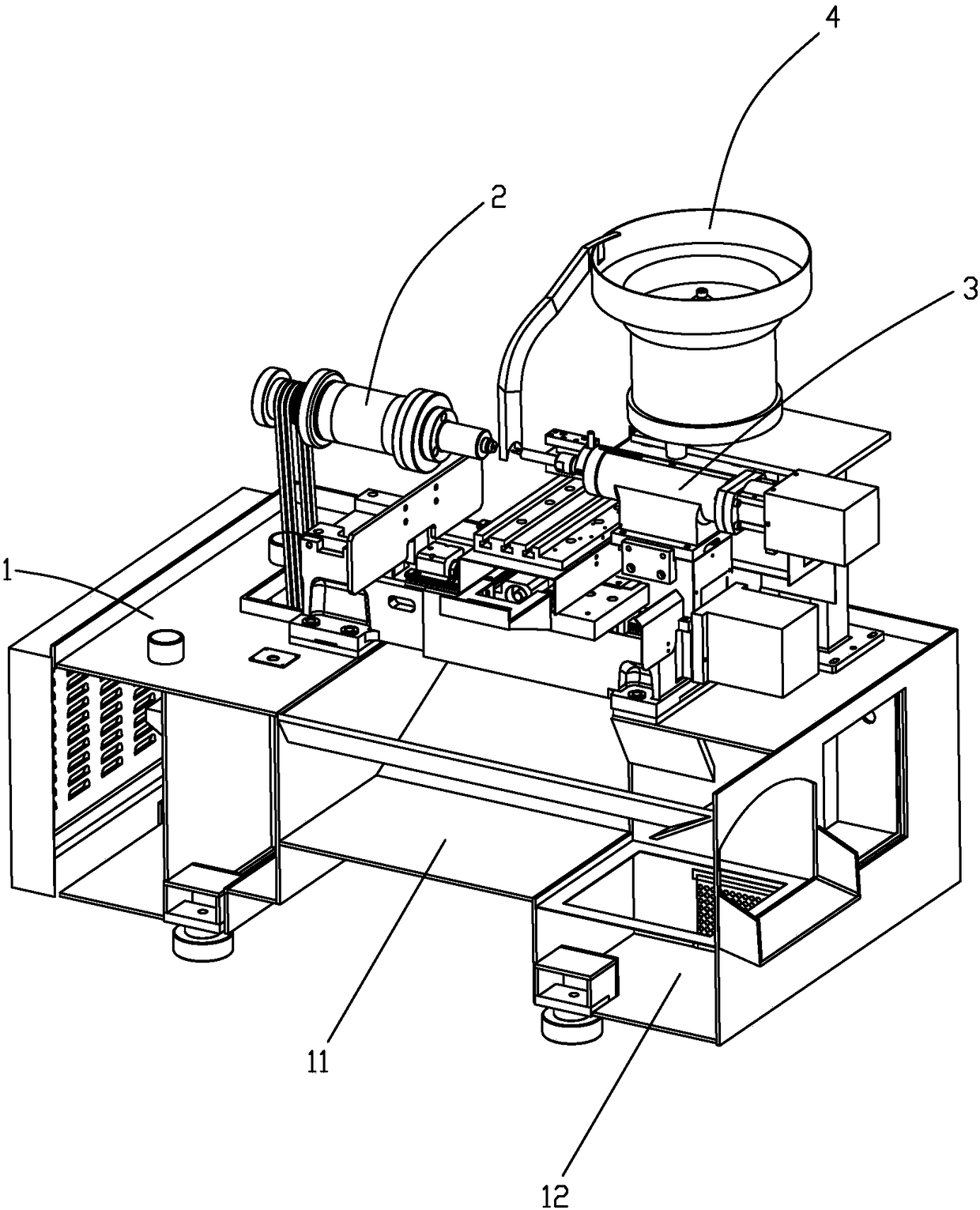
[0059] Such as Figure 1-2 As shown, the automatic numerical control processing equipment used in the production of guide wheels includes frame 1, rotating clamping device 2, constant force tailstock 3, feeding device 4, cutting device, material receiving device, bus numerical control system 5 and pumping components .

[0060] Specifically, the rotating clamping device 2 is arranged on the upper left side of the frame 1 for clamping and rotating the workpiece. The constant force tailstock 3 is arranged on the upper right side of the frame 1, and is used to press the workpiece toward the left side of the frame 1. The feeding device 4 is arranged on the rear upper side of the frame 1 and is used to transport the workpiece between the cutting device 2 and the constant force tailstock 4 . The cutting device is arranged on the rea...


PUM


Abstract

The invention discloses automatic numerical control machining equipment applied to guide wheel production. The automatic numerical control machining equipment comprises a rack, a rotary clamping device arranged on the upper left side of the rack, a constant force tailstock arranged on the upper right side of the rack, a feeding device arranged on the upper back side of the rack, a cutting device arranged on the back side of the constant force tailstock, a receiving device arranged on the front side of the constant force tailstock and a bus numerical control system arranged on the rack and electrically connected with the rotary clamping device, the constant force tailstock, the feeding device, the cutting device and the receiving device. According to the automatic numerical control machining equipment, the feeding device automatically conveys workpieces to the position between the rotary clamping device and the constant force tailstock, the rotary clamping device and the constant forcetailstock are matched to clamp the workpieces, then the workpieces are cut through the cutting device, the workpieces fall into the receiving device after machining is completed, the full-process automatic machining aim is achieved, the machining accuracy of the workpieces is guaranteed, the quality requirement of the machined workpieces can be improved to the greatest extent, the unqualified rateis reduced, and meanwhile, enterprise large-scale production is facilitated for meeting the higher market requirement.

Description

【Technical field】 [0001] The present application relates to the technical field of guide wheel production equipment, in particular to an automatic numerical control processing equipment applied to guide wheel production. 【Background technique】 [0002] Since entering the 21st century, with the continuous development of numerical control technology and the expansion of application fields, numerical control processing equipment such as numerical control milling machines and numerical control lathes have played an increasingly important role in important industries such as IT, automobiles, light industry, and medical treatment, because The digitization of equipment required by these industries has become a major trend of modern development. [0003] However, when the existing CNC machining equipment for the guide wheel cuts the arc position on the circumference of the guide wheel, it cannot realize fully automatic machining, and it still needs to manually load and unload the wo...

Claims


Application Information

Patent Timeline
Patent Type & Authority Applications(China)
IPC IPC(8): B23Q37/00B23Q7/00B23Q7/14
CPCB23Q7/00B23Q7/14B23Q37/00
Inventor 汪国君晏昭勇罗健文吴伟明
Owner 中山市誉胜智能科技有限公司
Learn More