
Stapleless stapler

A stapler and punching pin technology, applied in binding and other directions, can solve the problems of destroying the orderliness of original documents, tearing of paper fixing holes, and consumption of staples, so as to facilitate popularization and use, reduce resource consumption, and prolong The effect of service life

Pending Publication Date: 2018-10-16
郭宣言
View PDF0 Cites 4 Cited by
  • Summary
  • Abstract
  • Description
  • Claims
  • Application Information

AI Technical Summary

Problems solved by technology

[0002] The staplers commonly used in the past were used with staples. On the one hand, the staples need to be consumed. On the other hand, the staples need to be removed in advance when using the shredder to destroy the bound documents, which is time-consuming and laborious. convenient
At present, there are needleless staplers on the market, and there are two common ones: one is an embossed needleless stapler, and the other is a long-hole reverse-folding lock-type, which is temporarily defined here as "lock-free stapler". Needle binding machine", these two binding machines can solve the defects of the use of the needle stapler, but each has a new defect: the embossed needleless binding machine is not firm in binding, and it is easy for the pages to come off after binding. It is easy to lose the front and back pages of the document; the lock needleless binding machine improves the firmness of the binding compared with the embossed needleless binding machine, but leaves a large binding hole on the paper after binding, which affects the appearance In addition, when the bound document is re-divided into single pages for copying and other operations, it is easy to tear the paper fixing hole, and the original binding hole is not easy to restore, which destroys the orderliness of the original document. Black spots are left on copies

Method used


Image

  • Stapleless stapler
  • Stapleless stapler
  • Stapleless stapler

Examples


Embodiment Construction

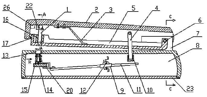
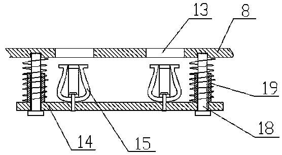
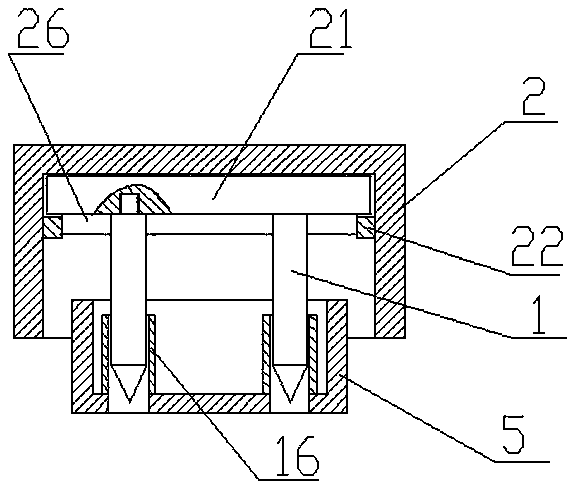
[0032] refer to figure 1 — Figure 13, a needleless stapler, including a gland and a base, the gland is located above the base, a paper pressing groove 5 is set in the inner cavity of the gland 2, the end of the gland 2, the paper pressing groove and the base 8 The ends are hinged together by the same pin shaft 6. The gland 2 is a lid with an open lower end. A leaf spring 3 is arranged in the inner cavity of the gland 2, and the upper end of the leaf spring is fixedly connected to the top surface of the gland 2. , the lower end of the plate spring 3 leans against the inner bottom surface of the paper press groove 5, and a punch support shaft is mounted on the top of the inner cavity of the cover 2, and two pin support shafts are vertically fixed on the outer peripheral surface of the punch support shaft 21. Two alternate tines 1, the tines support shaft 21 and the axes of the two tines 1 are on the same plane, the paper pressing groove 5 is a groove body with an open upper en...


PUM


Abstract

The invention relates to a stapleless stapler. The stapleless stapler comprises a pressing cover and a base, wherein a paper pressing groove is formed in an inner cavity of the pressing cover; the tail ends of the pressing cover, the paper pressing groove and the base are hinged together by the same pin shaft; a plate spring leaf is arranged in the inner cavity of the pressing cover; the upper endof the plate spring leaf is fixedly connected to the top surface of the pressing cover; the lower end of the plate spring leaf abuts against the inner bottom surface of the paper pressing groove; a punching needle supporting shaft is also hooked on the top of the inner cavity of the pressing cover; two punching needles are fixed on the peripheral surface of the punching needle supporting shaft; two guide cylinders are fixed in an inner cavity of the paper pressing groove; two needle holes corresponding to the punching needles are formed in the upper end surface of the base; a top plate is arranged in a cavity of the base; two elastic clamps are fixedly arranged on the upper end surface of the top plate; the lower ends of the elastic clamps are fixedly connected to the top plate; and elastic clamping openings are reserved at the upper ends of the elastic clamps. The stapleless stapler can easily staple several pieces of paper together with no need of staples, facilitates the reductionof consumption of resources and firmly staples the paper; and the page disconnection phenomenon is unlikely to occur after stapling.

Description

technical field [0001] The invention belongs to the technical field of office supplies, and in particular relates to a needleless stapler. Background technique [0002] The staplers commonly used in the past were used with staples. On the one hand, the staples need to be consumed. On the other hand, the staples need to be removed in advance when using the shredder to destroy the bound documents, which is time-consuming and laborious. Convenience. At present, there are needleless staplers on the market, and there are two common ones: one is an embossed needleless stapler, and the other is a long hole reversing lock type, which is temporarily defined as "lock without lock" Needle binding machine", these two binding machines can solve the defects of the use of the needle stapler, but each has a new defect: the embossed needleless binding machine is not firm in binding, and it is easy for the pages to come off after binding. It is easy to lose the front and back pages of the d...

Claims


Application Information

Patent Timeline
IPC IPC(8): B42B5/02
CPCB42B5/02
Inventor 郭宣言
Owner 郭宣言
Learn More