Novel high-speed magnetic suspension train and suspension mechanism

A magnetic array and suspension surface technology, applied in vehicle components, electric vehicles, electric traction, etc., can solve the problems of large power consumption, high energy consumption, heavy cooling system, etc., and achieve low electromagnetic pollution, low energy consumption, and maintenance. The effect of low operating costs

Pending Publication Date: 2018-10-16
胡铁林
View PDF8 Cites 3 Cited by
  • Summary
  • Abstract
  • Description
  • Claims
  • Application Information

AI Technical Summary

Problems solved by technology

[0003] At present, China, Japan, Germany, Britain, the United States and other countries are actively researching maglev trains. At present, China mainly studies low- and medium-speed maglev trains. The main technology of high-speed maglev trains is in the hands of Japan and Germany, and they are divided into two categories in terms of structure. One is a high-speed constant-conduction maglev train represented by Germany. This type of suspension has a small air gap and a speed of 400-500 kilometers per hour, which is suitable for long-distance rapid transportation between cities. The other is based on The superconducting maglev train represented by Japan has a large air gap, but its speed can reach more than 500 kilometers per hour. The train floats, although the above-mentioned maglev technology has many advantages, there are still some shortcomings, such as: 1. Since the maglev system

Method used


Image

  • Novel high-speed magnetic suspension train and suspension mechanism
  • Novel high-speed magnetic suspension train and suspension mechanism
  • Novel high-speed magnetic suspension train and suspension mechanism

Examples


Embodiment Construction

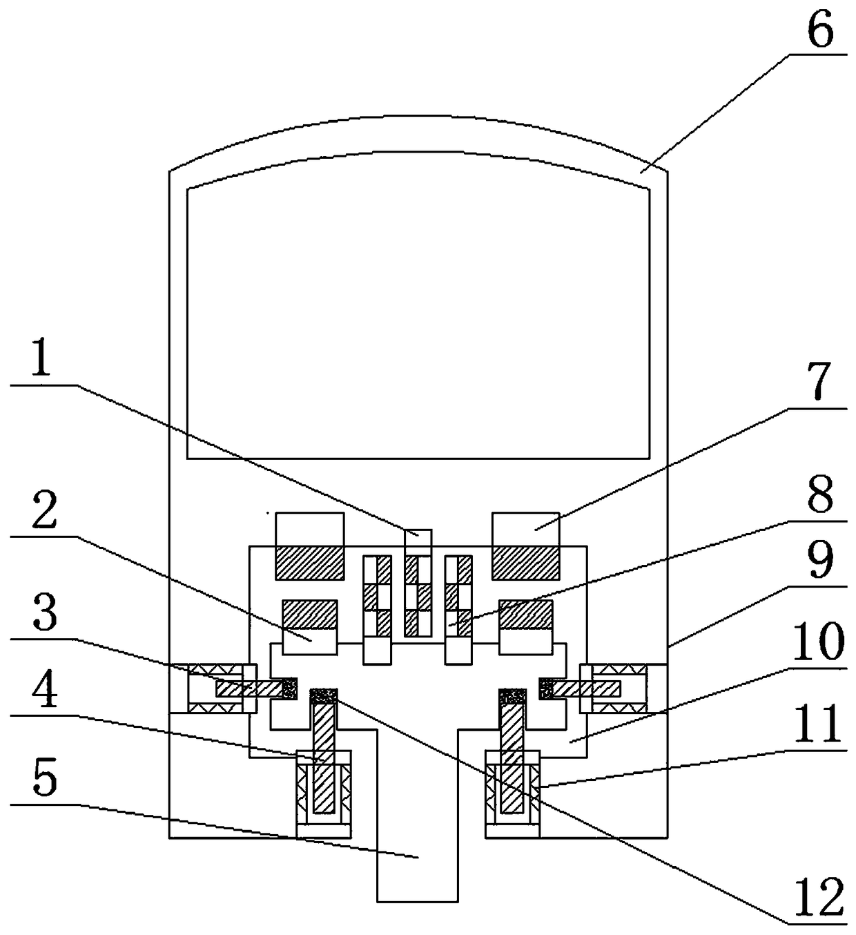
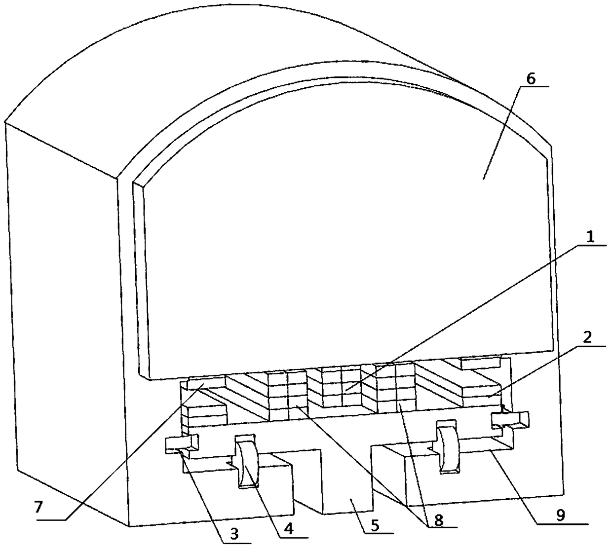
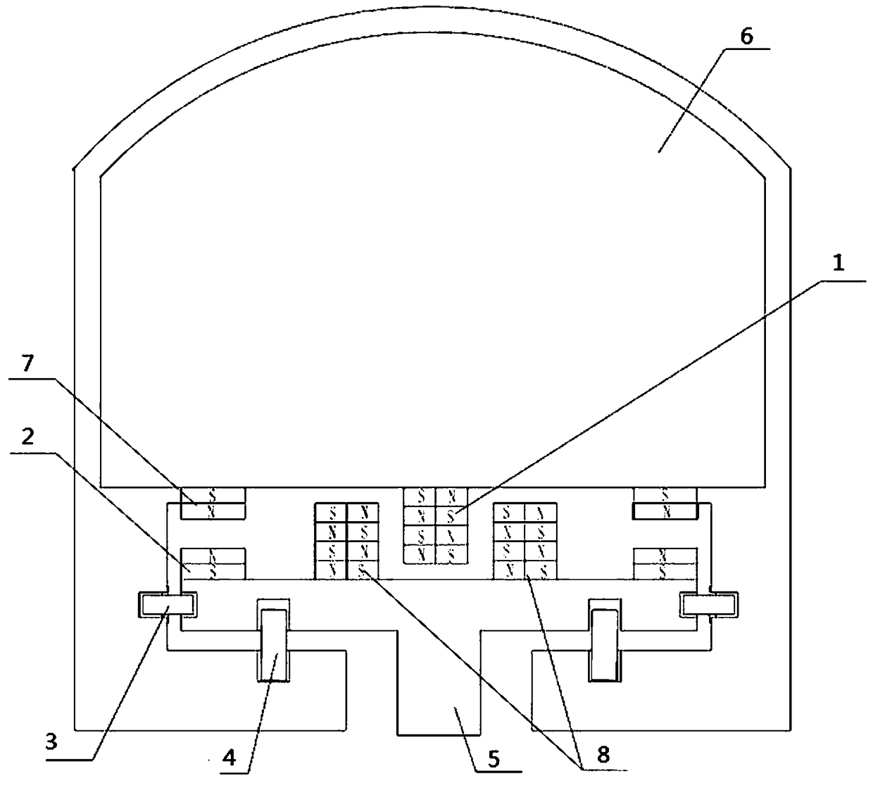
[0027] In order to fully explain the implementation of the present invention, the implementation examples of the present invention are provided below, and these examples are only illustrations of the present invention and do not limit the scope of the present invention.

[0028] In the description of the present invention, it should be noted that the terms "center", "upper", "lower", "left", "right", "vertical", "horizontal", "inner", "outer" etc. The indicated orientation or positional relationship is based on the orientation or positional relationship shown in the drawings, and is only for the convenience of describing the present invention and simplifying the description, rather than indicating or implying that the referred device or element must have a specific orientation, or in a specific orientation. construction and operation, therefore, should not be construed as limiting the invention. In addition, the terms "first", "second", and "third" are used for descriptive pur...


PUM


Abstract

The invention relates to a novel high-speed magnetic suspension train structure, in particular to a novel high-speed magnetic suspension train and a suspension mechanism with simple structure and lowelectromagnetic pollution. The novel high-speed magnetic suspension train comprises a train body and a track arranged opposite to the train body and extending in the driving direction of the train body; a track groove is formed in the bottom of the train body, and the track is arranged in the track groove; the track groove is of a semi-closed concave groove structure, and an accommodating cavity is formed in the track groove; and a balancing magnet device, a suspension magnetic device, a transverse power-assisted wheel group and a longitudinal active power wheel group are correspondingly arranged in the accommodating cavity, wherein the balancing magnet device and the suspension magnetic device are used for the matching action of the track groove and the track, and the transverse power-assisted wheel group and the longitudinal active power wheel group are used for the sliding matching of the track groove and the track. According to the novel high-speed magnetic suspension train, a permanent magnet provides suspension force for supporting the train, the energy consumption is low, the service life is long, the electromagnetic pollution is low, and maintenance and operation cost is low. The novel high-speed magnetic suspension train has simple structure and good use performance.

Description

technical field [0001] The invention relates to a novel high-speed magnetic levitation train structure, in particular to a novel high-speed magnetic levitation train and a levitation mechanism with simple structure and low electromagnetic pollution. Background technique [0002] A maglev train is a train propelled by magnetic levitation force, that is, magnetic attraction and repulsion. Because the magnetic force of its track separates the contact surface between the train and the track and reduces friction, the maglev train has high speed, stable and comfortable operation, easy to realize automatic control, no noise, no harmful exhaust gas, which is beneficial to environmental protection and can be used It has many advantages such as saving construction expenses, low operation, maintenance and energy consumption costs, and it is an ideal super express train in the 21st century. All countries in the world attach great importance to the development of maglev trains. [0003]...

Claims


Application Information

Patent Timeline
IPC IPC(8): B60L13/04
CPCB60L13/04
Inventor 胡铁林李鑫胡金林孙玺朱成浩李弗能崔宇刘海明张峻溪黄福恒程少杰陈铁胡晓娟李志勇李佐佑尔李日华赵桂辰马意洋
Owner 胡铁林
Why Eureka
Try Eureka