Liquid filling device and liquid filling system

A technology of liquid filling and liquid pressure, applied in liquid materials, packaging, transportation and packaging, etc., can solve the problems of low filling efficiency, inability to meet high-speed filling production, and inability to perform filling operations, and achieve filling efficiency. high effect

Pending Publication Date: 2018-10-16
XIAMEN INTRETECH +1
View PDF11 Cites 2 Cited by
  • Summary
  • Abstract
  • Description
  • Claims
  • Application Information

AI Technical Summary

Problems solved by technology

The cost of the traditional linear filling device is low, but the filling efficiency of the linear filling device is low, which cannot meet the high-speed filling production
[0004] In addition, for the liquid to be perfused with a large filling volume and high viscosity, none of the existing filling devices can perform filling operations efficiently

Method used


Image

  • Liquid filling device and liquid filling system
  • Liquid filling device and liquid filling system
  • Liquid filling device and liquid filling system

Examples


no. 1 example

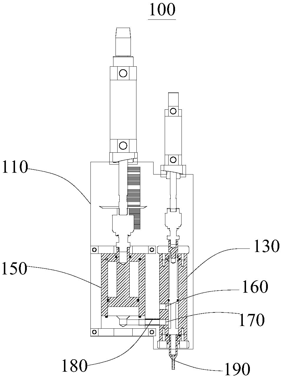
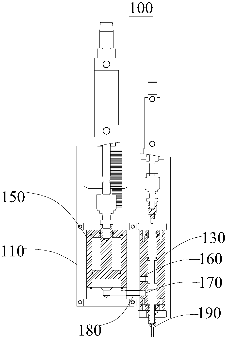
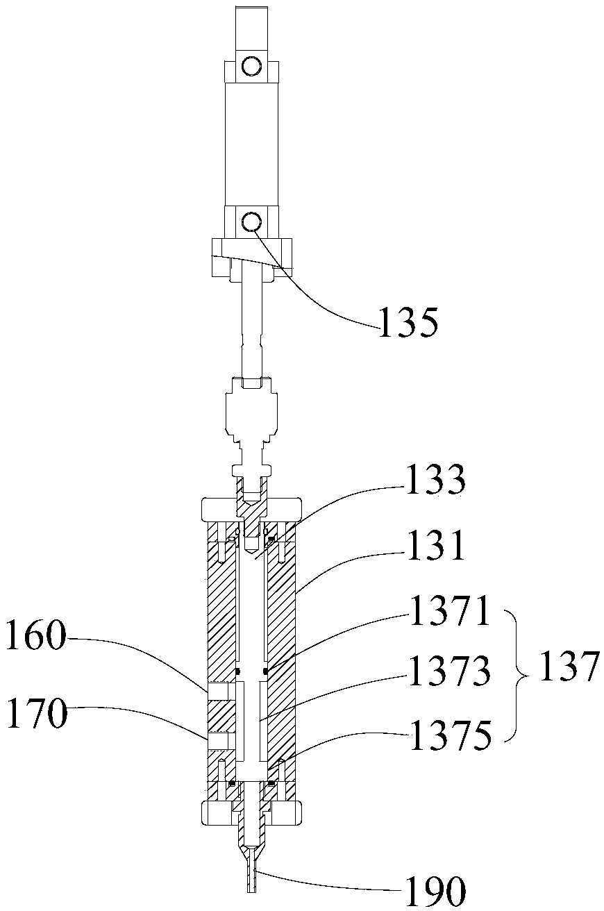
[0034] see in conjunction Figure 1 to Figure 4, the present embodiment provides a liquid perfusion device 100, including a cylinder fixed base plate 110, a first liquid injection cylinder 130 and a second liquid injection cylinder 150, the first liquid injection cylinder 130 and the second liquid injection cylinder 150 are both arranged on On the fixed base plate 110 of the cylinder body, a first interface 160 and a second interface 170 are opened on the first liquid injection cylinder 130, the first interface 160 is used to connect the liquid pressure barrel, the second interface 170 is provided with an external connection pipe 180, the first interface 160 is selectively communicated with the second interface 170, and the two ends of the external connection pipe 180 are respectively connected with the first liquid injection cylinder 130 and the second liquid injection cylinder 150, so that the inner cavity of the first liquid injection cylinder 130 and the second liquid injec...

no. 2 example

[0046] This embodiment provides a liquid perfusion system, including a liquid pressure tank (not shown in the figure) and a liquid perfusion device 100, wherein the basic structure and principle of the liquid perfusion device 100 and the technical effects produced are the same as those of the first embodiment, for brief For the description, for parts not mentioned in this embodiment, reference may be made to the corresponding content in the first embodiment.

[0047] The liquid filling device 100 includes a cylinder body fixed base plate 110, a first liquid injection cylinder 130 and a second liquid injection cylinder 150, the first liquid injection cylinder 130 and the second liquid injection cylinder 150 are both arranged on the cylinder body fixed base plate 110, the second liquid injection cylinder 130 A liquid injection cylinder 130 is provided with a first port 160 and a second port 170, the second port 170 is provided with an external connection pipe 180, the first port ...


PUM


Abstract

The invention provides a liquid filling device and a liquid filling system, and relates to the technical field of workpiece liquid filling. The liquid filling device comprises a cylinder body fixing base plate, a first liquid filling cylinder and a second liquid filling cylinder, wherein the first liquid filling cylinder and the second liquid filling cylinder are arranged on the cylinder body fixing base plate, the first liquid filling cylinder is provided with a first connector and a second connector, the first connector is used for being connected with a liquid pressure barrel, the second connector is provided with an outer connecting pipe, the first connector selectively communicates with the second connector, the two ends of the outer connecting pipe are connected with the first liquidfilling cylinder and the second liquid filling cylinder respectively, one end of the first liquid filling cylinder is provided with a liquid filling nozzle, and the liquid filling nozzle selectivelycommunicates with the second interface. According to the liquid filling device, the second liquid filling cylinder is used for extracting, storing and filling liquid, so that the liquid to be poured in the liquid pressure barrel can be quickly extracted and filled into the liquid pressure barrel, the filling efficiency is high, and meanwhile the filling requirements of the high-liquid-volume high-viscosity filling liquid can be met.

Description

technical field [0001] The invention relates to the technical field of workpiece liquid injection, in particular to a liquid injection device and a liquid injection system. Background technique [0002] In the process of mechanical manufacturing, it is often necessary to fill the workpiece with various liquids such as lubricating fluid or filling fluid, which is often realized by filling devices. [0003] According to the different running trajectories of the container during the filling process, the filling device is mainly divided into a rotary filling device and a linear filling device. The filling efficiency of the rotary filling device is high, but the equipment cost of the rotary filling device is very high, and the rotary filling device will continuously generate reflux while filling, and the liquid reflux volume is large, and the liquid reflux volume will be large. Accounting for about one-third of the total container filling volume, the returned liquid needs to be ...

Claims


Application Information

Patent Timeline
Patent Type & Authority Applications(China)
IPC IPC(8): B65B3/12
CPCB65B3/12
Inventor 林元泽李金苗曾敏超
Owner XIAMEN INTRETECH
Why Eureka
Try Eureka