Automatic sewage transfer station

A transfer station, sewage technology, applied in the direction of light water/sewage treatment, water/sewage multi-stage treatment, water/sludge/sewage treatment, etc. problem, to achieve the effect of volume reduction, weight reduction, and good filtering effect

Inactive Publication Date: 2018-10-16
福建省中卫安职业卫生工程科学研究院
View PDF0 Cites 0 Cited by
  • Summary
  • Abstract
  • Description
  • Claims
  • Application Information

AI Technical Summary

Problems solved by technology

[0003] The main purpose of the present invention is to provide an automatic sewage transfer station, which can effectively solve the problem in the background art that often found in some garbage transfer stations that the connection is not timely. Pull it away in time. The existing garbage transfer station does not have the function of discharging the sewage in the garbage, which will cause certain pollution in the garbage transfer station after the garbage is compressed. The environment of the transfer station is seriously damaged. Afterwards, the garbage needs to be transported away. Due to the compression, the garbage is easy to get stuck in the compression box and it is difficult to clean up. Moreover, when not in use, the remaining stains in the garbage transfer station breed bacteria and seriously affect the surrounding environment.

Method used


Image

  • Automatic sewage transfer station
  • Automatic sewage transfer station
  • Automatic sewage transfer station

Examples


Embodiment

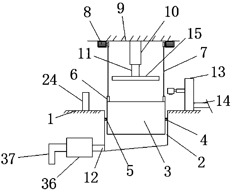
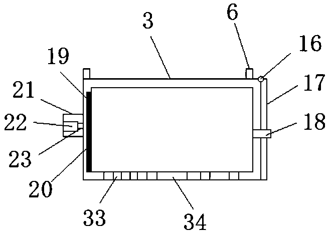
[0028] refer to Figure 1-6 , an automatic sewage transfer station, including a ground 1, a box body 3, a sewage pipe 12, a pressure plate 15, a second hydraulic cylinder 22 and a third hydraulic cylinder 29, the top of the ground 1 is provided with a groove 2, and the concave The inner cavity of the groove 2 is provided with a box body 3, and the left and right side walls of the box body 3 are equipped with a placement block 5, and the left and right side walls of the inner cavity of the groove 2 are equipped with a limit block 5, and the placement block 4 is placed on the top of the limit block 5, and the four corners of the top of the box body 1 are equipped with connecting blocks 6, and the top of the connecting block 6 is connected with one end of a connecting rope 7, and the other end of the connecting rope 7 is connected to At the outer end of the drive shaft of the motor 8, the motor 8 is mounted on the top of the wall 9, the middle of the top of the wall 9 is equipped...


PUM


Abstract

The invention discloses an automatic sewage transfer station. The automatic sewage transfer station comprises a floor, a box body, a blowdown pipe, a press plate, a second hydraulic cylinder and a third hydraulic cylinder, wherein the top part of the floor is provided with a groove; the box body is arranged in an inner cavity of the groove; placing blocks are respectively arranged at the left sidewall and right side wall of the box body; limiting blocks are arranged at the left side wall and right side wall of the inner cavity of the groove; each placing block is put at the top part of the corresponding limiting block. The automatic sewage transfer station has the advantages that the data is fed back to a processor through a gravity sensor; when the weight reaches the preset value, the processor automatically starts the first hydraulic cylinder, a first piston rod drives a press plate to press down, and the garbage in the box body is compressed, so that the size of the garbage is reduced; meanwhile, the sewage flows away via a through hole, so that the weight is reduced; when the compression and blowdown are completed, the processor sends a signal to a garbage conveying center viaa wireless module, so as to provide the prompt for a user that the garbage needs to be timely carried away; more practicality is realized, and the automatic sewage transfer station is suitable for being widely popularized and applied.

Description

technical field [0001] The invention relates to a garbage transfer station, in particular to an automatic sewage transfer station. Background technique [0002] With the continuous improvement of people's living standards, the requirements for environmental conditions are also increasing. The traditional garbage stations in urban and rural areas can no longer meet people's requirements for new concepts such as high efficiency, environmental protection, energy saving and low consumption. Therefore, the promotion of compressed garbage stations is inevitable. must do. The compressed garbage transfer station is leading the development of the garbage transfer station industry due to its small footprint, good concealment, and reasonable space structure. The existing garbage transfer station is to place the garbage somewhere and compress it to reduce its volume. It is often found that the connection of the existing garbage transfer stations is not timely. In the case of a lot of g...

Claims


Application Information

Patent Timeline
Patent Type & Authority Applications(China)
IPC IPC(8): C02F9/08B65F9/00
CPCB65F9/00C02F1/001C02F1/32C02F2301/08C02F2303/04C02F2303/14
Inventor 陈阳阳庄景阳
Owner 福建省中卫安职业卫生工程科学研究院
Why Eureka
Try Eureka