Method for arranging large deep foundation pit bidirectional annular ramps

A deep foundation pit, annular technology, applied in the field of transportation, can solve the problems of fixed entrance range of trestle ramps, unable to form a circular route, unfavorable for the walking of muck trucks, etc., to shorten the construction period, high stability and rigidity, and stable vehicle operation. Effect

Inactive Publication Date: 2021-05-28
SHANGHAI BAOYE GRP CORP
View PDF5 Cites 0 Cited by
  • Summary
  • Abstract
  • Description
  • Claims
  • Application Information

AI Technical Summary

Problems solved by technology

[0002] When constructing some complex large-scale comprehensive squares, most of them need to build multi-layers underground. During the construction process, foundation pits need to be excavated. When excavating foundation pits, a large number of excavating equipment and vehicles are required. In addition, it is necessary to transport a large number of soil clods produced by excavation to avoid the accumulation of soil clods and thus affect the construction of the foundation pit. How to get the muck vehicles and mechanical equipment down to the bottom of the pit ensures that the transportation of muck trucks is convenient and the efficiency of excavation is increased. The key to deep foundation pit construction, so how to set up the ramp of the trestle bridge is very important. In the conventional foundation pit support design, a straight slope for the lower foundation pit will be set in the middle of the foundation pit, but the conventional inclined trestle ramp cannot A circular route is formed, and the entrance range of the trestle ramp is fixed and narrow, which is not conducive to the walking of muck trucks, and the excavation efficiency is low

Method used


Image

  • Method for arranging large deep foundation pit bidirectional annular ramps
  • Method for arranging large deep foundation pit bidirectional annular ramps

Examples


Embodiment Construction

[0025] The following description serves to disclose the present invention to enable those skilled in the art to carry out the present invention. The preferred embodiments described below are only examples, and those skilled in the art can devise other obvious variations.

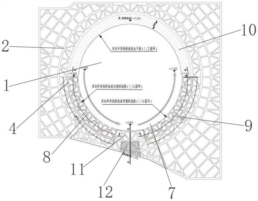
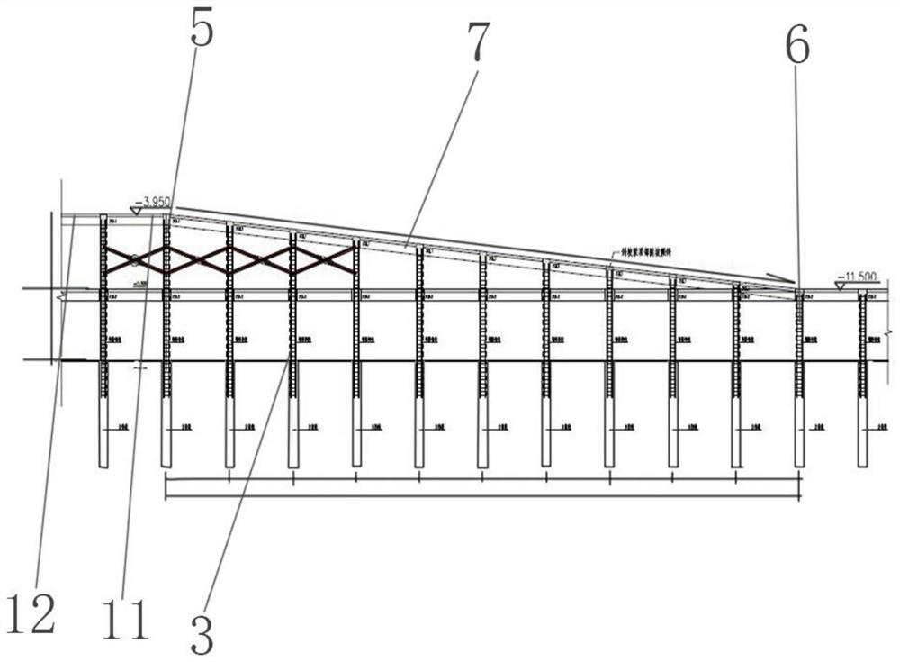
[0026] like Figure 1-2 The shown method for setting a two-way circular ramp for a large deep foundation pit, including the foundation pit (1), includes the following steps:

[0027] The first step is to collect site information, measure and determine the location and size of the site.

[0028] Establishing the data and dimensions of the site can facilitate the subsequent construction and avoid the problems of depression and collapse during the construction process.

[0029] In the second step, according to the measurement results of the first step, it is determined that the foundation pit 1 is a square-like shape, the depth of the foundation pit 1 is calculated, and excavation is carried out.

[0030] Af...


PUM


Abstract

The invention relates to the technical field of traffic, and particularly relates to a method for arranging large deep foundation pit bidirectional annular ramps. A foundation pit is included. The method comprises the following steps that 3, the ground height is calculated, the proper size is determined, supports are arranged on the periphery of the foundation pit, and the supports are supported through cast-in-place piles, a first annular reinforced concrete inner support and a second annular reinforced concrete inner support; 4, the bidirectional annular ramps are arranged between the ground and the second annular reinforced concrete inner support along the inner side edge of the first annular reinforced concrete inner support and the inner side edge of the second annular reinforced concrete inner support to be connected with the foundation pit; and 6, a short ramp is arranged on the ground to be connected with the bidirectional annular ramps on the two sides. The device is reasonable in design, and through the arrangement of the supports and the bidirectional annular ramps, vehicle instruments needed by construction can conveniently enter a site during construction, soil blocks generated by excavation can be conveniently conveyed out, and safety of the construction process is improved.

Description

technical field [0001] The invention relates to the field of transportation, in particular to a method for setting a two-way circular ramp in a large deep foundation pit. Background technique [0002] When constructing some complex large-scale comprehensive squares, most of them need to build multi-layers underground. During the construction process, foundation pits need to be excavated. When excavating foundation pits, a large number of excavating equipment and vehicles are required. In addition, it is necessary to transport a large number of soil clods produced by excavation to avoid the accumulation of soil clods and thus affect the construction of the foundation pit. How to get the muck vehicles and mechanical equipment down to the bottom of the pit ensures that the transportation of muck trucks is convenient and the efficiency of excavation is increased. The key to deep foundation pit construction, so how to set up the ramp of the trestle bridge is very important. In th...

Claims


Application Information

Patent Timeline
Patent Type & Authority Applications(China)
IPC IPC(8): E02D17/02E02D17/04E02D5/34E01D15/12E01C9/08E01D101/26
CPCE02D17/02E02D17/04E02D5/34E01D15/12E01C9/086E02D2300/002E01D2101/26
Inventor 张家和张艳超臧言礼
Owner SHANGHAI BAOYE GRP CORP
Why Eureka
Try Eureka