Eureka AIR delivers breakthrough ideas for toughest innovation challenges, trusted by R&D personnel around the world.

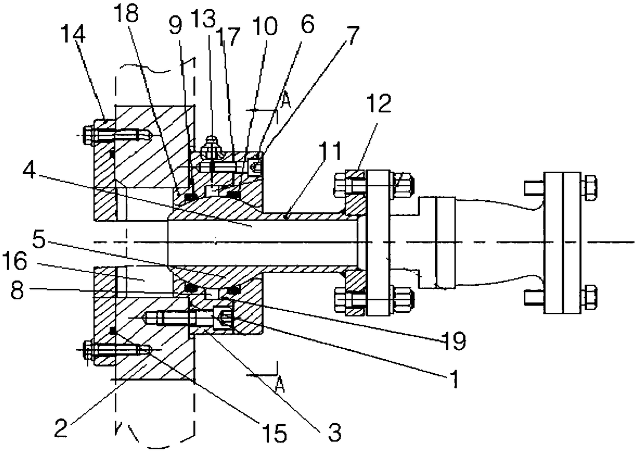
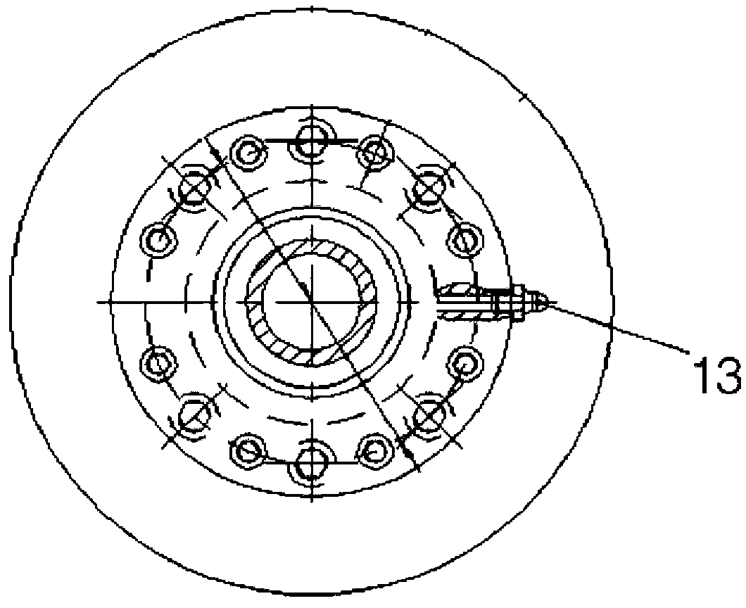
Full cross-section tunnel heading machine hinged type grouting joint

A technology of tunnel boring machine and grouting joint, applied in tunnels, tunnel lining, shaft lining and other directions, can solve problems such as affecting construction progress, reducing construction efficiency, and troublesome processing, saving resources and costs, improving work efficiency, The effect of reinforcing the stability

Pending Publication Date: 2018-10-16
辽宁三三工业有限公司
View PDF0 Cites 1 Cited by
  • Summary
  • Abstract
  • Description
  • Claims
  • Application Information

AI Technical Summary

Problems solved by technology

[0002] At present, there are many shortcomings in the vertical grouting system of the shield machine. For example, if the vertical grouting system is used in the second grouting, it will cause uneven grouting between the segment and the soil layer, resulting in gaps between the segment and the soil layer. , it is easy to cause ground subsidence and affect the construction progress
In addition, vertical grouting is likely to cause grout to block between the segment and the soil layer, and the processing process is very troublesome and reduces construction efficiency

Method used


Image

  • Full cross-section tunnel heading machine hinged type grouting joint
  • Full cross-section tunnel heading machine hinged type grouting joint

Examples


Embodiment Construction

[0019] It should be noted that, in the case of no conflict, the embodiments of the present invention and the features in the embodiments can be combined with each other.

[0020] In describing the present invention, it should be understood that the terms "center", "longitudinal", "transverse", "upper", "lower", "front", "rear", "left", "right", The orientations or positional relationships indicated by "vertical", "horizontal", "top", "bottom", "inner", "outer", etc. are based on the orientation or positional relationships shown in the drawings, and are only for the convenience of describing the present invention Creation and simplification of description, rather than indicating or implying that the device or element referred to must have a specific orientation, be constructed and operate in a specific orientation, and therefore should not be construed as limiting the invention. In addition, the terms "first", "second", etc. are used for descriptive purposes only, and should no...


PUM


Abstract

The invention provides a full cross-section tunnel heading machine hinged type grouting joint. The full cross-section tunnel heading machine hinged type grouting joint comprises a spherical hinge front seat fixed to a fixed block through a first connecting assembly and a spherical hinge rear seat installed on the ball head portion of a spherical hinge in a sleeving mode. The spherical hinge rear seat is fixed to the spherical hinge front seat through an adjusting connecting assembly, and a matching cavity rotatably matched with the spherical hinge is formed in the spherical hinge front seat and the spherical hinge rear seat. A first spherical hinge seal is arranged between the spherical hinge front seat and the ball head portion, and a second spherical hinge seal is arranged between the spherical hinge rear seat and the ball head portion. A first flange disc used for being connected with a grouting pipe is arranged at the tail end of the connecting part of the spherical hinge. A lubricating nipple used for injecting grease into the matching cavity is arranged on the spherical hinge front seat. When the grouting joint is used for grouting, grout between segments and soil is not prone to being blocked so that the grout can be fully distributed between the segments and the soil, the stability between the segments is strengthened, the ground is protected from collapsing, work efficiency is improved, and resources and costs are reduced.

Description

technical field [0001] The invention belongs to the technical field of tunnel boring machine equipment, and in particular relates to an articulated grouting joint of a full-section tunnel boring machine. Background technique [0002] At present, there are many shortcomings in the vertical grouting system of the shield machine. For example, if the vertical grouting system is used in the second grouting, it will cause uneven grouting between the segment and the soil layer, resulting in gaps between the segment and the soil layer. , It is easy to cause ground subsidence and affect the construction progress. In addition, the vertical grouting is easy to cause the grout to block between the segment and the soil layer, and the processing process is very troublesome and reduces the construction efficiency. There is an urgent need to improve the existing grouting system to avoid the occurrence of gaps between the segment and the soil layer, which will reduce the construction qualit...

Claims


Application Information

Patent Timeline
Patent Type & Authority Applications(China)
IPC IPC(8): E21D9/087E21D11/10E21D11/08
CPCE21D9/0873E21D11/08E21D11/105
Inventor 刘子铭刘晓东
Owner 辽宁三三工业有限公司
Why Eureka
Eureka Blog
Learn More