A new type of wheel-side reduction structure and reducer

A wheel-side deceleration and deceleration unit technology, used in mechanical equipment, gear transmissions, belts/chains/gears, etc., can solve the problems of large wheel-side deceleration structure, poor compactness, long working time, etc., to meet the requirements of transmission deceleration. ratio of demand, high compactness and reasonable structure

Active Publication Date: 2021-06-04
SHANTUI CONSTR MASCH CO LTD
View PDF5 Cites 0 Cited by
  • Summary
  • Abstract
  • Description
  • Claims
  • Application Information

AI Technical Summary

Problems solved by technology

However, the main technical problems in the existing technology include: multi-stage planetary gears need to be equipped with multiple planetary ring gears correspondingly, so that the structure of the entire wheel-side reduction structure is relatively large and the compactness is poor; at the same time, on some heavy-duty reducers, the It is necessary to output greater torque at a lower speed. The existing three-stage reduction unit is difficult to provide greater torque because of the small transmission ratio. Higher speed is required to save time and fuel consumption. The existing three-stage deceleration structure cannot realize high and low gear operation according to working conditions, resulting in higher fuel consumption and longer working hours

Method used


Image

  • A new type of wheel-side reduction structure and reducer
  • A new type of wheel-side reduction structure and reducer
  • A new type of wheel-side reduction structure and reducer

Examples


Embodiment 1

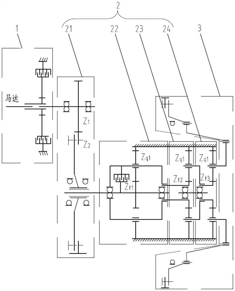
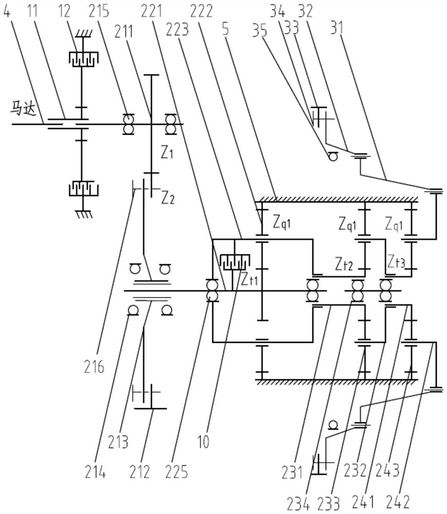
[0031] The invention provides a wheel-side deceleration structure, such as Figure 1-3 As shown, it mainly includes a brake unit 1, a transmission system 2, a drive unit 3 and a planetary ring gear 5, wherein the transmission system 2 includes a first-stage reduction unit 21, a second-stage reduction unit 22, a third-stage reduction unit 23 and a fourth-stage reduction unit 24 , wherein the first-stage reduction unit 21 includes a two-stage spur gear reduction structure, the second-stage reduction unit 22 includes a first planetary row structure and the clutch 10, the third-stage reduction unit 23 includes a second planetary row structure, and the fourth-stage reduction unit 24 includes a second planetary row structure. Two star row structure. A plurality of corresponding planetary gears in the secondary reduction unit 22 , the tertiary reduction unit 23 and the fourth reduction unit 24 are all internally meshed with the planetary ring gear 5 . The brake unit 1 is connected t...

Embodiment 2

[0057] The present invention also provides a speed reducer, such as Figure 5 As shown in the schematic diagram of the travel operation of the reducer, it includes: an engine 61 providing power output, a coupling 62 and a pump 7 connected to the motor 4, the coupling 62 is respectively connected to the engine 61 and the pump 7, and the motor 4 is connected to the corresponding wheel. Edge deceleration structure. The pump 7 and the motor 4 constitute a closed walking hydraulic system. That is, the oil circulates between the pump 7 and the motor 4, the pump 7 converts the torque provided by the engine 61 into high-pressure oil, and the high-pressure oil transfers energy to the motor 4, and then the motor 4 converts the oil flow into torque again Drive sprocket wheel hub 33, promote crawler belt walking.

[0058] Preferably, the speed reducer includes a left wheel-side reduction structure 81 and a right wheel-side reduction structure 82, the pump 7 includes a rear pump 71 and a...


PUM


Abstract

The invention discloses a novel wheel edge reduction structure and a reducer, and relates to the technical field of reducers. The wheel-side reduction structure includes a brake unit, a transmission system and a drive unit connected in sequence. The brake unit is connected to the output end of the motor. The first-stage reduction unit in the transmission system includes a two-stage spur gear reduction structure, and the second-stage reduction unit includes the first planetary gear ring and clutch, the three-stage reduction unit includes the second planetary ring gear, the four-stage reduction unit includes the third planetary ring gear; and the first planetary ring gear, the second planetary ring gear, and the third planetary ring gear form a planetary structure The ring gear and the planetary ring gear are internally meshed with a plurality of correspondingly arranged planetary gears. Also disclosed is a speed reducer, which is connected with at least one above-mentioned wheel edge speed reduction structure. The reduction ratio of the wheel-side reduction structure is higher, the structure is more reasonable, and the compactness is higher; at the same time, the reducer can realize high and low speed gear operation according to the working conditions, so as to better meet the requirements of the working conditions.

Description

technical field [0001] The invention relates to the technical field of reducers, in particular to a novel wheel-side reduction structure and a reducer. Background technique [0002] The two types of wheel-side reduction structures commonly used in reducers include two-stage spur gear reduction structure and planetary gear reduction structure. Among them, the two-stage spur gear wheel-side reduction structure is simple, the structure size is large, and the components are unbalanced. And it cannot be modularized, and maintenance is inconvenient. [0003] The planetary gear reduction structure in the prior art adopts a three-stage reduction unit, wherein the first-stage reduction unit includes a two-stage spur gear reduction structure, and the second-stage and third-stage reduction units are planetary row structures, the purpose of which is to obtain a larger transmission ratio . However, the main technical problems in the existing technology include: multi-stage planetary ge...

Claims


Application Information

Patent Timeline
Patent Type & Authority Patents(China)
IPC IPC(8): F16H1/46F16H57/023
CPCF16H1/46F16H57/023
Inventor 续鲁宁张如伟康正生侯文军
Owner SHANTUI CONSTR MASCH CO LTD
Why Eureka
Try Eureka