Supercharge Your Innovation With Domain-Expert AI Agents!

E3F2 stacked power amplifier with high gain and high efficiency for precise harmonic control

A technology of power amplifier and harmonic control, applied in power amplifiers, amplifiers, amplifiers with semiconductor devices/discharge tubes, etc., can solve the problem of low power output capability and power gain capability, low broadband output capability and efficiency, and limited amplifier Working bandwidth and other issues to achieve the effect of small circuit size, high gain, and suppression of gate-source leakage

Pending Publication Date: 2018-10-16
CHENGDU GANIDE TECH
View PDF6 Cites 2 Cited by
  • Summary
  • Abstract
  • Description
  • Claims
  • Application Information

AI Technical Summary

Problems solved by technology

However, in the design of traditional high-efficiency power amplifiers, there have always been some design problems, mainly reflected in the mutual restriction of high-efficiency indicators: in order to ensure the high-efficiency operation of the amplifier, the transistor must work in the overdrive mode, similar to the switch state, but The bandwidth of the overdrive switching power amplifier has always been the technical bottleneck of circuit realization
[0003] There are many circuit structures of common high-efficiency power amplifiers, the most typical ones are traditional class AB, class C, switching type power amplifiers of class D, class E, and class F, etc. However, there are still some shortcomings in the broadband characteristics of these high-efficiency amplifiers. , which is mainly reflected in: the theoretical limit efficiency of the traditional class AB amplifier is 78.5%, which is relatively low, and it is often necessary to sacrifice the output insertion loss and efficiency to increase the bandwidth of the amplifier; the limit efficiency of the class C amplifier is 100%, but the power output capability is low. The broadband output capability and efficiency are low; switching type D, E, F power amplifiers, etc. need to rely on precise harmonic impedance control, or strict impedance matching conditions, these controls and conditions greatly limit the operating bandwidth of the amplifier
In addition, the existing high-efficiency FET power amplifiers are often implemented based on a single common-source transistor, which is limited by a single transistor, and the power output capability and power gain capability are relatively low

Method used


Image

  • E3F2 stacked power amplifier with high gain and high efficiency for precise harmonic control
  • E3F2 stacked power amplifier with high gain and high efficiency for precise harmonic control

Examples


Embodiment Construction

[0017] Exemplary embodiments of the present invention will now be described in detail with reference to the accompanying drawings. It should be understood that the implementations shown and described in the drawings are only exemplary, intended to explain the principle and spirit of the present invention, rather than limit the scope of the present invention.

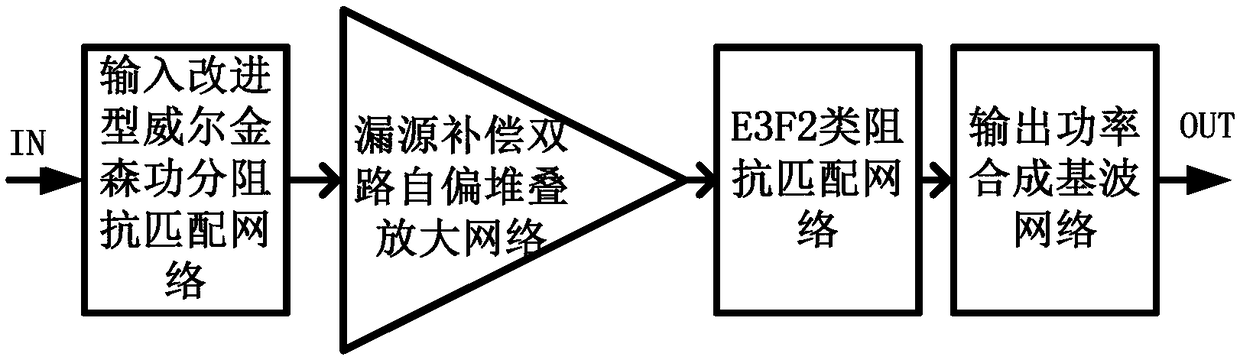
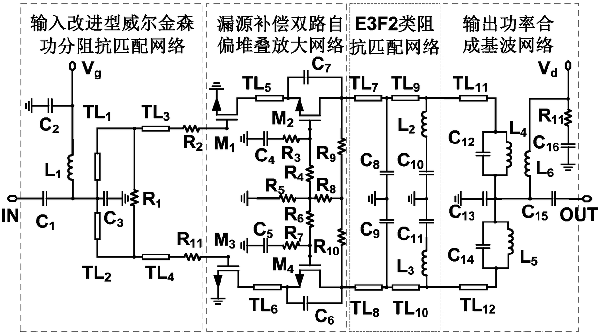
[0018] Embodiments of the present invention provide an E3F2 class stacked power amplifier with precise harmonic control, high gain and high efficiency, such as figure 1 As shown, it includes the input improved Wilkinson power division impedance matching network, the drain-source compensation dual-channel self-biased stacking amplifier network, the E3F2 impedance matching network and the output power synthesis fundamental wave network; the input improved Wilkinson power The input end of the sub-impedance matching network is the input end of the entire E3F2 stacked power amplifier, its first output end is connected to the ...


PUM


Abstract

The invention discloses an E3F2 stacked power amplifier with high gain and high efficiency for precise harmonic control. The power amplifier comprises an input-improved Wilkinson power divider impedance-matching network, a self-bias stacked amplification network for drain-source compensation with dual channels, an E3F2 impedance-matching network and an output power synthetic fundamental network. The power amplifier adopts a self-bias dual-stacked transistor structure based on drain-source compensation with the dual channels, and combines a high-efficiency E3F2 output matching network, so thata circuit can realize accurate control on the fundamental wave and harmonic impedance of the output impedance of the E3F2 amplifier. The power amplifier can control peak voltage between Class F and Class E by combining the similarities of output impedance circuits of Class F and Class E amplifiers, which alleviates the design pressure of the peak voltage of a transistor, and has high efficiency, high gain, high power output capability and small circuit dimensions.

Description

technical field [0001] The invention belongs to the technical field of field effect transistor radio frequency power amplifiers and integrated circuits, and in particular relates to the design of an E3F2 class stacked power amplifier with precise harmonic control, high gain and high efficiency. Background technique [0002] With the development of modern military and civilian communication technologies, RF front-end transmitters are also developing in the direction of high efficiency, high gain, and high power output. Therefore, the market urgently needs high-efficiency, high-gain, high-power power amplifiers. However, in the design of traditional high-efficiency power amplifiers, there have always been some design problems, mainly reflected in the mutual restriction of high-efficiency indicators: in order to ensure the high-efficiency operation of the amplifier, the transistor must work in the overdrive mode, similar to the switch state, but The bandwidth of the overdrive ...

Claims


Application Information

Patent Timeline
Patent Type & Authority Applications(China)
IPC IPC(8): G06F17/50H03F3/193H03F3/21
CPCH03F3/193H03F3/21G06F30/36
Inventor 胡柳林邬海峰滑育楠陈依军吕继平童伟王测天
Owner CHENGDU GANIDE TECH
Features
  • R&D
  • Intellectual Property
  • Life Sciences
  • Materials
  • Tech Scout
  • Unparalleled Data Quality
  • Higher Quality Content
  • 60% Fewer Hallucinations
Learn More