
Board repairing method based on PCBA board poor welding spot infrared positioning and correcting apparatus

A bad solder joint, infrared technology, applied in the direction of printed circuit maintenance/correction, printed circuit secondary processing, etc., can solve the problems of low work efficiency, low work efficiency, high labor intensity, etc., to improve work efficiency and save correction time. , structurally reliable effect

Inactive Publication Date: 2018-10-16
DONGGUAN AOHAI TECH CO LTD
View PDF4 Cites 0 Cited by
  • Summary
  • Abstract
  • Description
  • Claims
  • Application Information

AI Technical Summary

Problems solved by technology

[0002] There are a large number of electronic components welded on the PCBA board, and there are inevitably bad solder joints. It is necessary to inspect the PCBA board and repair the position of the bad solder joints. In the prior art, manual kanban is usually used. Repairing, that is, picking up the entire PCBA board manually, and carefully observing the specific conditions at each solder point, the labor intensity is high, the work efficiency is low, and it is easy to miss inspections, which affects the consistency of the product; There is a situation where solder joint inspection is performed while manual repairing is performed corresponding to the detected bad solder joints. This method requires the operator to frequently raise the head to check the bad solder joints and lower the head to perform manual repair welding, which increases eye and neck fatigue. degree, it is easy to cause cervical spine strain and low work efficiency

Method used


Image

  • Board repairing method based on PCBA board poor welding spot infrared positioning and correcting apparatus
  • Board repairing method based on PCBA board poor welding spot infrared positioning and correcting apparatus
  • Board repairing method based on PCBA board poor welding spot infrared positioning and correcting apparatus

Examples


Embodiment Construction

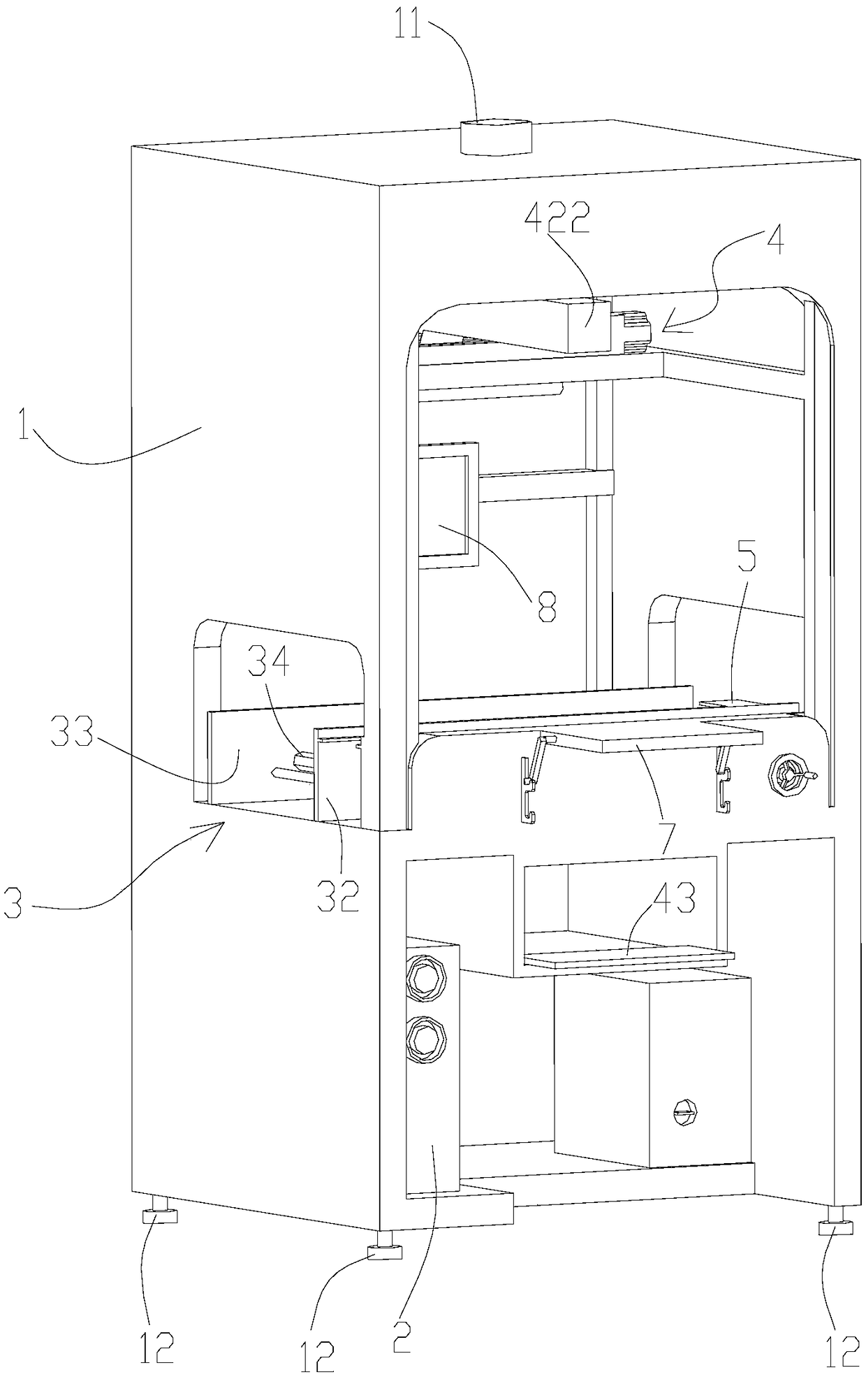
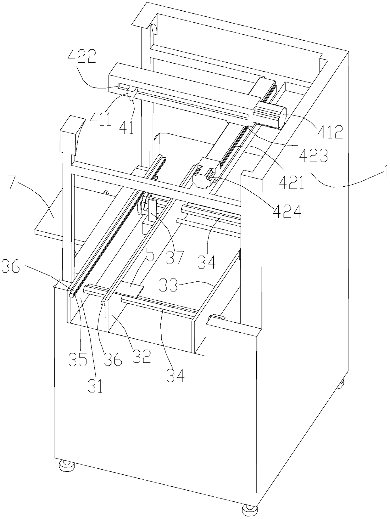
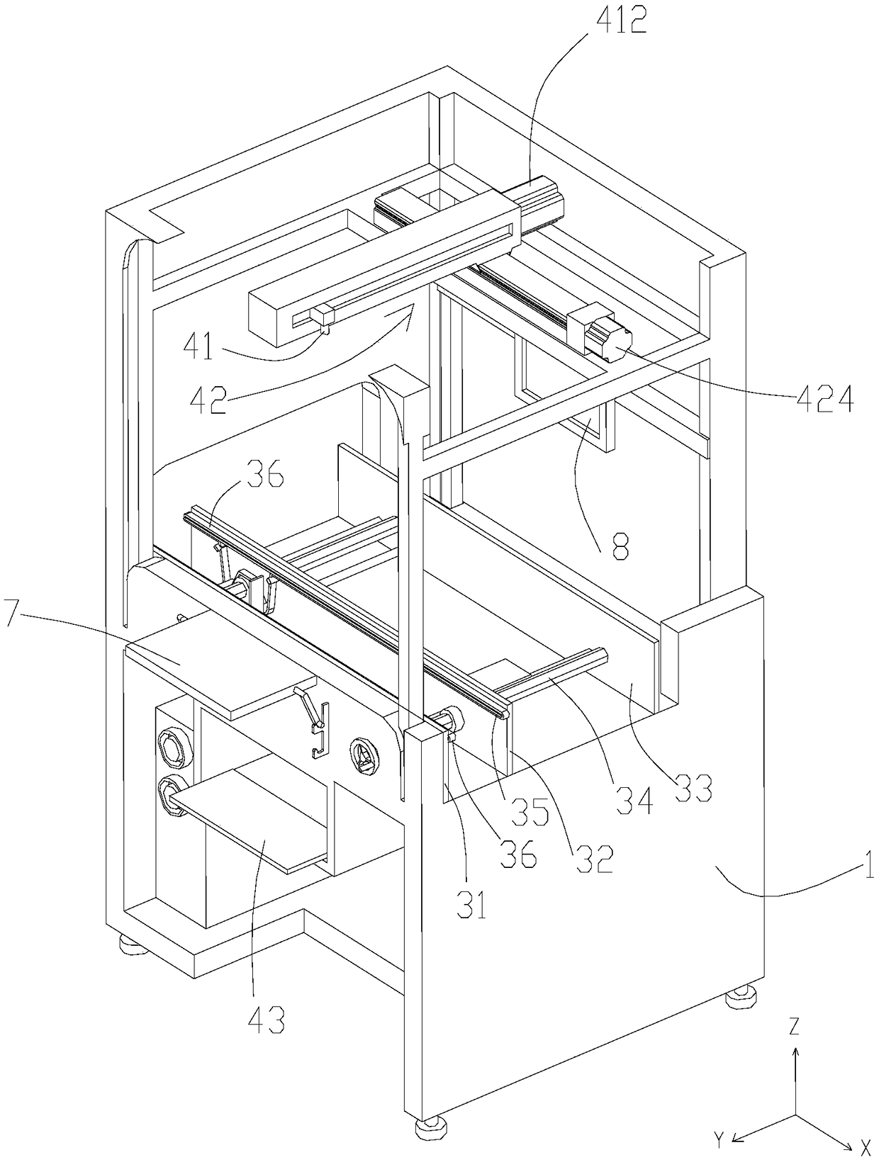
[0023] For the convenience of description, such as image 3 The Chinese text is shown as a reference, defining that the PCBA board flows from the previous process to the next process in the X direction, on the same plane as the X direction, and the direction perpendicular to the X direction is the Y direction; the direction perpendicular to the plane where XY is located is the Z direction.

[0024] Such as Figure 1-3 As shown, an infrared positioning correction device for bad solder joints of a PCBA board includes a frame 1, a host computer 2 that stores coordinate information of bad solder joints of a PCBA board to be corrected, an automatic transmission device 3, and can transfer bad solder joints of a PCBA board to be corrected. The infrared positioning system 4 indicated one by one, and the display screen 8 that can display the bad solder spot position image stored in the main frame 2; The main frame 2, automatic transmission device 3, infrared positioning system 4, displ...


PUM


Abstract

The invention discloses a board repairing method based on a PCBA board poor welding spot infrared positioning and correcting apparatus. The correcting apparatus comprises a rack, a host for storing to-be-corrected PCBA board poor welding spot coordinate information, an automatic transmission apparatus, an infrared positioning system, a display screen and a PLC control system; the automatic transmission apparatus is arranged in an X direction and runs through the two ends of the rack; a stop operation mechanism used for enabling the to-be-corrected PCBA board on the automatic transmission apparatus to stop moving in a lifting up process and enabling the corrected PCBA board to move along with the automatic transmission apparatus in a lifting down process is arranged between the two sides ofthe automatic transmission apparatus; and the infrared positioning system is correspondingly arranged above the automatic transmission apparatus, and comprises an infrared indicator lamp, a dual-railmovement assembly for driving the indicator lamp to perform reciprocating motion in the X and Y directions, and a keyboard for controlling the infrared indicator lamp to move from a former poor welding spot to the next poor welding spot. By adoption of the board repairing method, convenience in use and accurate positioning are realized; and the infrared positioning system can indicate the poor welding spots one by one and can be used for PCBA boards of different widths.

Description

technical field [0001] The invention relates to the field of PCBA board processing, in particular to a board repairing method using an infrared positioning correction device for defective solder joints of a PCBA board. Background technique [0002] There are a large number of electronic components welded on the PCBA board, and there are inevitably bad solder joints. It is necessary to inspect the PCBA board and repair the position of the bad solder joints. In the prior art, manual kanban is usually used. Repairing, that is, picking up the entire PCBA board manually, and carefully observing the specific conditions at each solder point, the labor intensity is high, the work efficiency is low, and it is easy to miss inspections, which affects the consistency of the product; There is a situation where solder joint inspection is performed while manual repairing is performed corresponding to the detected bad solder joints. This method requires the operator to frequently raise the ...

Claims


Application Information

Patent Timeline
Patent Type & Authority Applications(China)
IPC IPC(8): H05K3/22
CPCH05K3/225
Inventor 万泽兵刘昊欧阳军张家栋金磊吴强
Owner DONGGUAN AOHAI TECH CO LTD
Learn More