
Grape peeling machine

A peeling machine and grape technology, which is applied in the peeling of vegetables or fruits, juice extraction, food science, etc., can solve the problems of low peeling efficiency, complicated process, affecting the taste and freshness of grape pulp, and improve the work efficiency. Efficiency and service life, the effect of simple structure

Inactive Publication Date: 2018-10-19
JIANGSU UNIV
View PDF4 Cites 0 Cited by
  • Summary
  • Abstract
  • Description
  • Claims
  • Application Information

AI Technical Summary

Problems solved by technology

[0004] In summary, the various grape peeling methods currently used in production are complicated in process and low in peeling efficiency, which cannot meet the needs of large-scale production. At the same time, some methods will also affect the taste and freshness of grape pulp.

Method used


Image

  • Grape peeling machine
  • Grape peeling machine

Examples


Embodiment 1

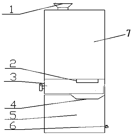
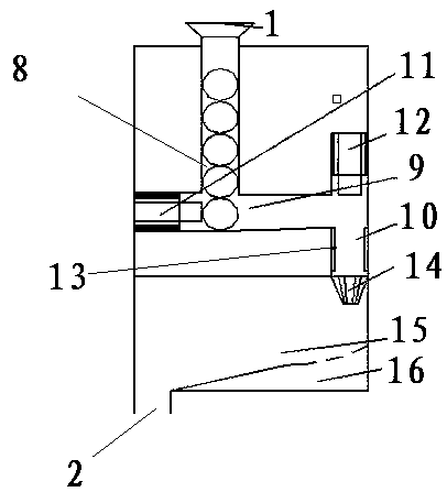
[0017] Embodiment one: if figure 1 and figure 2 As shown, the grape peeling machine of this embodiment includes a peeling box 7, the upper end of the peeling box 7 is provided with a grape inlet 1, and the lower end is provided with a pulp outlet 2, and a pulp collection box 3 is provided below the pulp outlet 2 , the pulp collection box 3 is detachably connected with the peeling box 7. The inside of the peeling box 7 is provided with a first vertical grape conveying chamber 8, a horizontal grape conveying chamber 9 and a second vertical grape conveying chamber 10, and the grape inlet 1 communicates with the first vertical grape conveying chamber 8 , the first vertical grape conveying chamber 8 communicates with the horizontal grape conveying chamber 9, the horizontal grape conveying chamber 9 communicates with the second vertical grape conveying chamber 10, and the horizontal grape conveying chamber 9 is provided with There is a horizontal cylinder plug 11, a vertical cyli...

Embodiment 2

[0018] Embodiment 2: The technical solution of this embodiment is basically the same as that of Embodiment 1. The only difference is that there is no pulp collection box 3 in this embodiment, but a funnel 4 is used instead, and the lower part of the pulp outlet 2 is directly facing the funnel 4. , the output end of the funnel 4 is connected to the input end of the juice extractor 5, and the output end of the juice extractor 5 is connected to the fruit juice outlet 6, wherein the funnel 4 and the juice extractor 5 are all installed in the peeling box 7, the juice outlet 6 is installed on the wall of the peeling box 7.

[0019] The operation principle of this device is: put the grapes after simple soaking into the grape inlet 1, and the grapes enter the first vertical grape conveying chamber 8 along the grape inlet 1 until the first vertical grape conveying chamber 8 is filled. Full of grapes, when peeling, the horizontal cylinder plug 11 pushes the grapes to the bottom of the v...


PUM


Abstract

The invention relates to a grape peeling machine which comprises a peeling box. A grape inlet is formed in the upper end of the peeling box, and a pulp outlet is formed in the lower end of the peelingbox. A first vertical grape conveying cavity, a horizontal grape conveying cavity and a second vertical grape conveying cavity are formed in the peeling box, the grape inlet is communicated with thefirst vertical grape conveying cavity, the first vertical grape conveying cavity is communicated with the horizontal grape conveying cavity, and the horizontal grape conveying cavity is communicated with the second vertical grape conveying cavity. A horizontal air cylinder plug is arranged in the horizontal grape conveying cavity, a vertical air cylinder plug is arranged in an upper cavity body ofthe second vertical grape conveying cavity, a blade and a human-hand-shaped peeling claw are arranged in a lower cavity body of the second vertical grape conveying cavity in sequence, and a grape pulp conveying channel is arranged below the human-hand-shaped peeling claw and communicated with the pulp outlet. According to the grape peeling machine, by means of a simple mechanical structure, the function of completely stripping grape peel is achieved without influencing the completeness of grape pulp.

Description

technical field [0001] The invention relates to a peeling machine, which is suitable for the technical occasion of peeling grapes. Background technique [0002] Grapes are delicious and nutritious fruits that can be eaten directly or made into grape juice and wine. However, with the development of society, a large amount of pesticides have been put into agricultural products, making people wash the grapes very carefully before eating them. The cleaning process is very cumbersome and inconvenient, and some chemical cleaning agents will also affect the taste of the grapes. If the grapes are peeled and eaten, the process is also inconvenient, especially for large-scale food production. Some peeling methods currently on the market are mostly chemical methods, the process is complicated and chemical reagents are used, which not only affects the taste and freshness of grapes, but also the residual chemical reagents are harmful to the human body. [0003] For the peeling method...

Claims


Application Information

Patent Timeline
IPC IPC(8): A23N7/00A23N1/00
CPCA23N7/00A23N1/00
Inventor 杨志贤许正萱李晓龙霍晓东
Owner JIANGSU UNIV
Learn More