
A ladle watering vehicle for cleaning residues in the ladle

A ladle and slag technology, used in metal processing equipment, manufacturing tools, casting melt containers, etc., can solve the problems of splashing molten iron in the ladle, damage to the ladle, and inability to clean the bottom. Efficiency, solving the effect of molten iron splashing

Active Publication Date: 2020-02-18
TONGLING HEWU MACHINERY MFG
View PDF5 Cites 0 Cited by
  • Summary
  • Abstract
  • Description
  • Claims
  • Application Information

AI Technical Summary

Problems solved by technology

[0003] The present invention provides a ladle watering vehicle that is convenient for cleaning residues in the ladle, which can effectively solve the above-mentioned problems in the background technology that the current ladle watering vehicles commonly used in the market have poor stability during the process of transporting the ladle, and the ladle is prone to vibration. As a result, the internal molten iron is splashed, and at the same time, the turning mechanism of the ladle body is easily damaged under long-term high temperature conditions, resulting in the inability of the existing ladle watering vehicle to transport the molten iron, and the ladle cannot be used and must be scrapped. The existing ladle watering vehicle is inconvenient to accept the ladle transported by driving, and cannot effectively realize the cooperative use between the watering vehicle and the roof driving vehicle. At the same time, the bottom of the ladle contains a lot of residue during use. The existing ladle watering vehicle It cannot effectively clean the bottom, which will easily lead to the reduction of the purity of the molten iron and the damage of the ladle

Method used


Image

  • A ladle watering vehicle for cleaning residues in the ladle
  • A ladle watering vehicle for cleaning residues in the ladle
  • A ladle watering vehicle for cleaning residues in the ladle

Examples


Embodiment

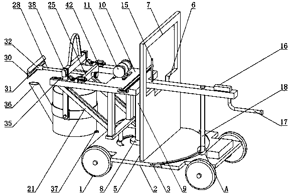
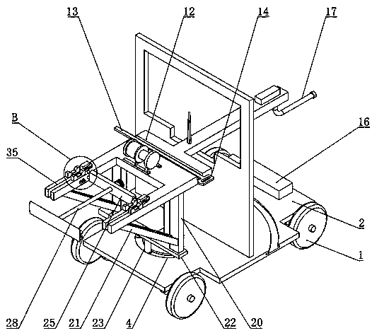
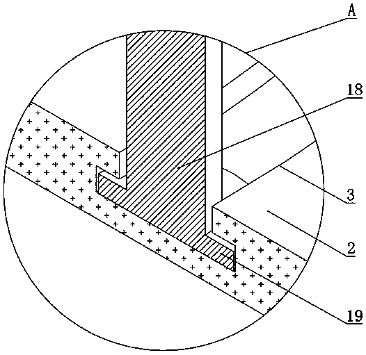
[0030] Example: such as Figure 1-6As shown, the present invention provides a technical solution, a ladle watering vehicle for easy cleaning of residues in the ladle, including a watering vehicle body 1, a mounting base plate 2, a first limiting groove 3, a second limiting groove 4, a protective Plate 5, movable notch 6, observation glass plate 7, bearing mount 8, fixed shaft 9, mounting frame 10, hoist 11, storage slot 12, rack 13, handle 14, calibration cylinder 15, counterweight 16, Push rod 17, first support rod 18, limit projection 19, first support column 20, second support column 21, fixed plate 22, second support rod 23, installation shaft 24, installation plate 25, cylindrical projection 26 , block 27, cleaning rod 28, connecting thread 29, scraper 30, waste slag storage tank 31, first threaded sleeve 32, second threaded sleeve 33, first gear 34, card slot 35, ladle 36, traction Ring 37, damping block 38, drying chamber 39, damping gasket 40, damping spring 41, mount...


PUM


Abstract

The invention discloses a ladle pouring vehicle facilitating cleaning of residues in a ladle. The ladle pouring vehicle comprises an installing frame, a winch, a scraper, a waste residue storage groove, a damping block and a damping gasket. The winch is arranged above the middle portion of the installing frame. The waste residue storage groove is formed in the middle portion of one side of the scraper. The damping gasket is arranged at the middle portion of the damping block. The ladle pouring vehicle is scientific and reasonable in structure and safe and convenient to use; the damping gasketand the damping spring are arranged, the up-down swinging frequency of the ladle in a clamping groove in the transportation process is reduced, and the situation that molten iron in the ladle is splashed is avoided. The scraper is arranged so that residues at the bottom of the ladle can be effectively scraped away, and the situation that the residues are congealed at the bottom of the ladle, and the purity of the molten iron is disturbed is avoided; and the installing frame and a push rod are arranged, the installing frame swings through cooperative installation of a fixing rotation shaft anda bearing block installing base, the clamping groove can better bear the ladle transported through a roof crane, and cooperative usage of a pouring vehicle body and the roof crane is facilitated.

Description

technical field [0001] The invention relates to the technical field of casting equipment, in particular to a ladle watering vehicle for cleaning residues in the ladle. Background technique [0002] Casting is a method of casting liquid metal into a casting cavity that is suitable for the shape of the part. After it is cooled and solidified, the method of obtaining parts or blanks is mostly the metal that is originally solid but heated to liquid state. The material can be sand, metal or even ceramics. Depending on the requirements, the method used will be different. During the pouring operation in the foundry, the ladle is used to receive the molten iron in front of the furnace, and then it is transported to the casting mold by a roofed truck. pouring, but during this process, the workers in the foundry workshop are relatively close to the ladle, which poses a great safety hazard, and accidents such as burns and ladle overturning are prone to occur. Therefore, the ladle assem...

Claims


Application Information

Patent Timeline
Patent Type & Authority Patents(China)
IPC IPC(8): B22D41/12B22D41/06B22D41/05
CPCB22D41/001B22D41/05B22D41/06B22D41/12
Inventor 张勇
Owner TONGLING HEWU MACHINERY MFG
Learn More