
Bearing platform device for pile foundation model test with adjustable rigidity and test method thereof

A model test and pile foundation technology, applied in the test of foundation structure, foundation structure engineering, construction, etc., can solve the problems of inconvenient conversion of rigid connection and hinge connection, non-removable reuse, poor working conditions, etc., and achieve easy maintenance and repair, Simple structure and low production cost

Active Publication Date: 2018-10-19
GUANGZHOU INSTITUTE OF BUILDING SCIENCE CO LTD
View PDF4 Cites 3 Cited by
  • Summary
  • Abstract
  • Description
  • Claims
  • Application Information

AI Technical Summary

Problems solved by technology

[0006] In order to solve the above problems, the present invention aims to provide a pile foundation model test cap device with adjustable restraint stiffness, so as to overcome the problem that the pile cap device in the prior art cannot be disassembled and reused, and can adapt to the poor conditions of multi-directional load action , The shortcomings of inconvenient conversion between rigid joint and hinged joint

Method used


Image

  • Bearing platform device for pile foundation model test with adjustable rigidity and test method thereof
  • Bearing platform device for pile foundation model test with adjustable rigidity and test method thereof
  • Bearing platform device for pile foundation model test with adjustable rigidity and test method thereof

Examples


Embodiment 1

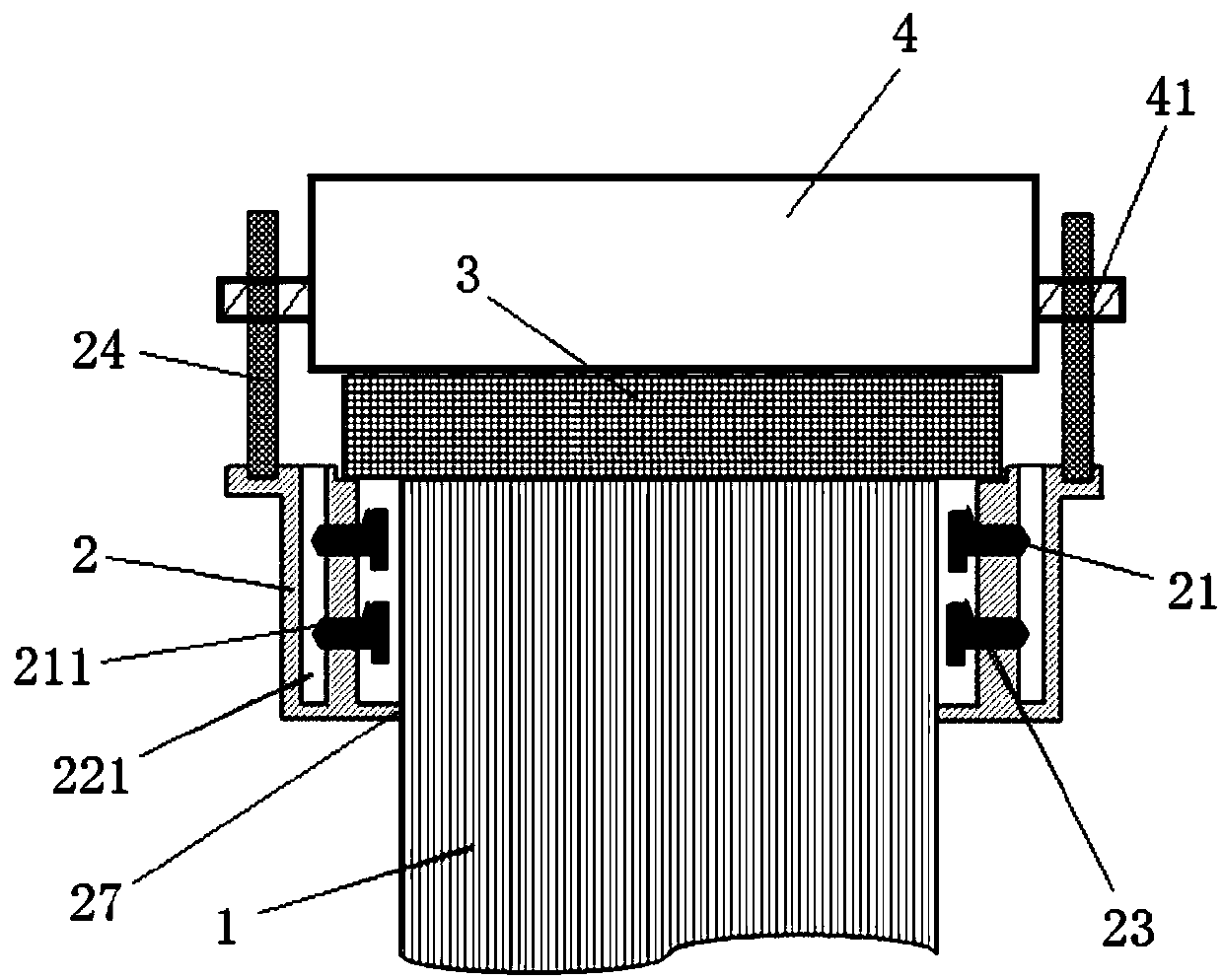
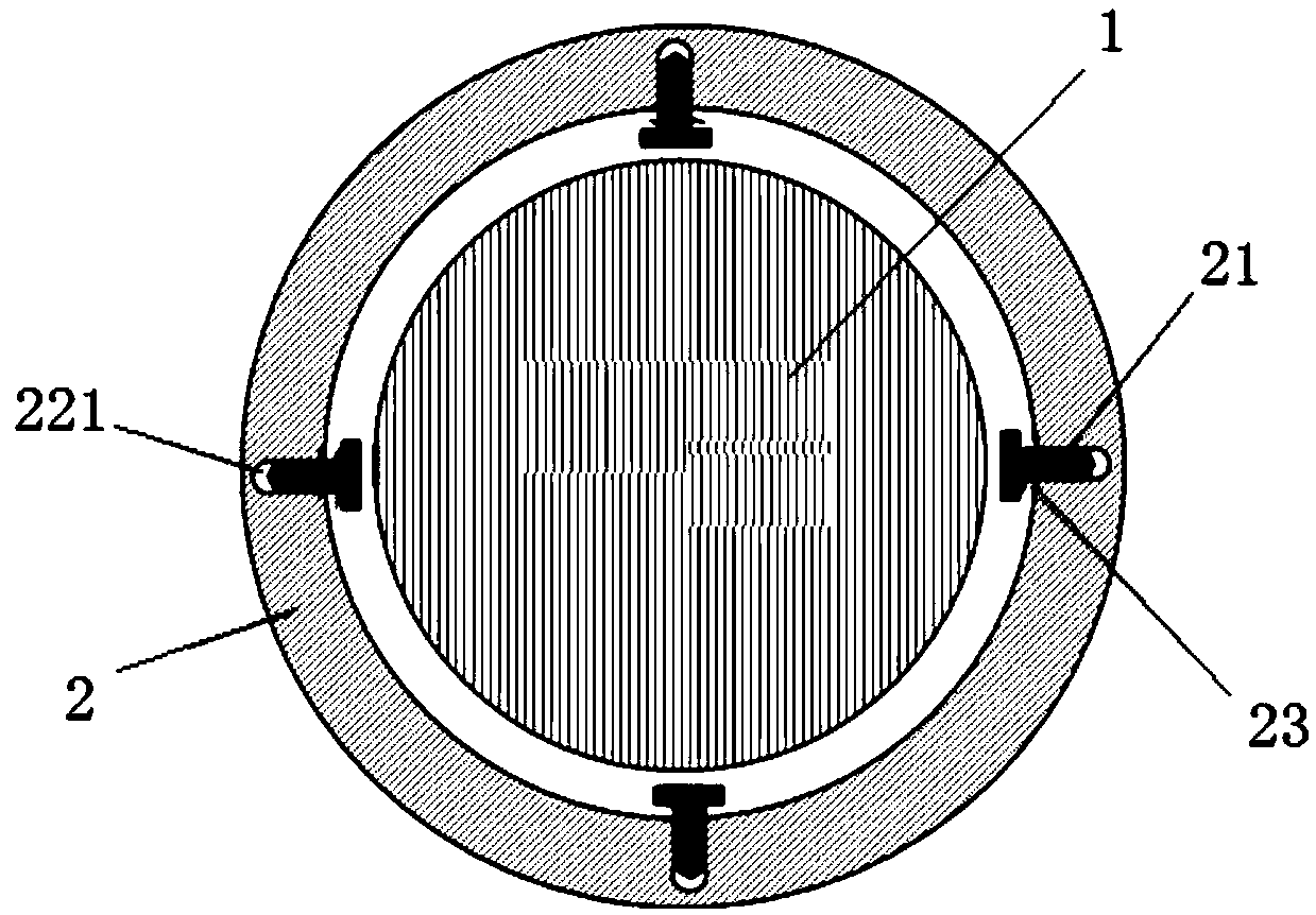
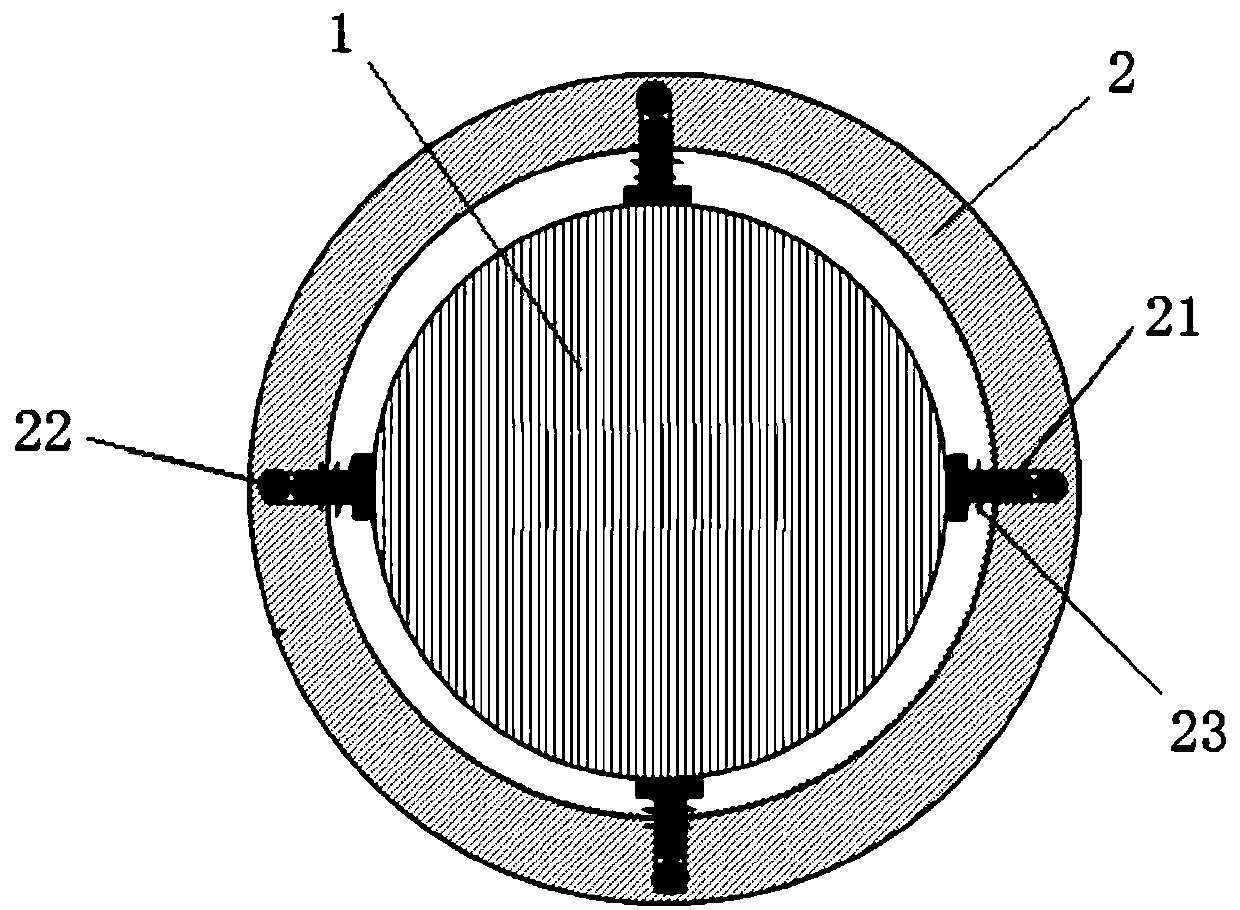
[0042] Such as Figure 1-4As shown, this embodiment provides a pile foundation model test cap device, including a cap frame 2 sleeved on the outside of the model pile 1, above the model pile 1 is provided with a device for applying vertical pressure to the The upper structure 4 of the model pile 1, a pressure sensor 3 and a backing plate (not shown in the figure) are sequentially arranged between the model pile 1 and the upper structure 4, and preferably, the pressure sensor 3 can be A pressure sensor commonly used in the market is selected, and the platform frame 2 is connected to the upper structure 4 through a connecting piece.

[0043] The inner side of the platform frame 2 is sequentially provided with a first concave surface 25, a second concave surface 26 with gradually smaller areas, and a through hole 27 connected to the model pile 1 in a gap from top to bottom. The second concave surface 26 The opening height is greater than the opening height of the first concave s...

Embodiment 2

[0051] In order to facilitate the understanding of this technical solution, based on the above cap device, here is a pile foundation model test method with adjustable constraint stiffness, such as Figure 5 shown, including the following steps:

[0052] Step 1: Embedding the model pile 1 into the soil of the model test until the height of the pile top meets the test requirements.

[0053] Step 2. According to the shape and size of the model pile 1, adjust the length of the sliding rod 213 of the ejector part 21 and the radian and length of the arc-shaped smooth contact surface 28, and select a pressure sensor 3 with a suitable diameter.

[0054] Step 3, select the shape and size of the first concave surface 25 according to the shape of the pressure sensor 3, and select the thickness of the backing plate according to the height and diameter of the pressure sensor 3;

[0055] Step 4: Connect the tension spring 23 between the top pressure block 212 of the ejection part 21 and th...


PUM


Abstract

The invention discloses a bearing platform device for a pile foundation model test, the invention further provides a test method based on the bearing platform device. The bearing platform device comprises a bearing platform framework which is arranged on the outer side of a model pile in a sleeved mode, an upper structure used for exerting vertical pressure is arranged above the model pile, a pressure sensor and a base plate are arranged between the model pile and the upper structure, the bearing platform framework is connected with the upper structure through a connecting piece, a second concave surface is arranged on the inner side of the bearing platform framework, a plurality of force applying devices used for exerting horizontal pressure are arranged on the side surface of the secondconcave surface, wherein the force applying device comprises an ejection part which is horizontally arranged, a force applying part which is vertically arranged and used for promoting the ejection part to abut against the model pile, and an elastic reset piece is arranged between the ejection part and the side face of the second concave surface. The bearing platform device aims to overcome the defect that the pile foundation bearing platform device in the prior art is not detachable and repeatedly utilized, and the defect that a rigid joint and a hinge joint are inconvenient to convert is overcome.

Description

technical field [0001] The invention belongs to the field of pile foundation engineering research in building construction, and in particular relates to a pile foundation model test cap device with adjustable restraint stiffness and a test method thereof. Background technique [0002] With the rapid development of the economy, there are more and more buildings, bridges, offshore, coastal and other projects under construction or already built. However, the pile foundations of these engineering structures are often directly or indirectly subjected to dynamic loads, such as seismic waves, waves, and wind loads. etc., will cause the dynamic interaction between the pile foundation supporting the superstructure and the soil. When the dynamic effect of the pile foundation reaches a certain level, it will cause a series of hazards, such as reducing the strength of the soil and excessive settlement of the pile foundation, which will lead to deformation and cracking of the upper struc...

Claims


Application Information

Patent Timeline
Patent Type & Authority Applications(China)
IPC IPC(8): E02D33/00
CPCE02D33/00Y02E10/50
Inventor 陈航唐孟雄胡贺松刘春林
Owner GUANGZHOU INSTITUTE OF BUILDING SCIENCE CO LTD
Learn More