Water drainage system of loess gully bridge site

A drainage system and gully technology, applied in waterway systems, sewer systems, water supply devices, etc., can solve the problems of double-wall corrugated pipes that cannot meet the drainage requirements, difficult treatment of pier pile foundations, and loss of drainage functions, etc. The cost of maintenance and maintenance, the avoidance of erosion and water damage, and the effect of simple structure

Pending Publication Date: 2018-10-19
SHANXI PROVINCIAL RES INST OF COMM
View PDF0 Cites 0 Cited by
  • Summary
  • Abstract
  • Description
  • Claims
  • Application Information

AI Technical Summary

Problems solved by technology

During the investigation of the lower part of the bridge, it was found that 90% of the rapid flow channels and drainage ditches of the loess gully bridge had water-damaged diseases such as basement subsidence, hollowing out, sinking, and fracture to varying degrees; Most of the bridge sites use large-diameter PVC double-wall corrugated pipes for temporary drainage. The double-wall corrugated pipes still cannot meet the drainage requirements, and the drainage function is partially or completely lost. There are serious safety hazards in the substructure of the bridge
Restricted by the topography of the bridge site and other conditions, it is extremely difficult to deal with the exposed pile foundation of the pier abutment. It is often necessary to carry out special protection and maintenance projects, which requires huge investment and an astonishing amount of work

Method used


Image

  • Water drainage system of loess gully bridge site
  • Water drainage system of loess gully bridge site
  • Water drainage system of loess gully bridge site

Examples


Embodiment 1

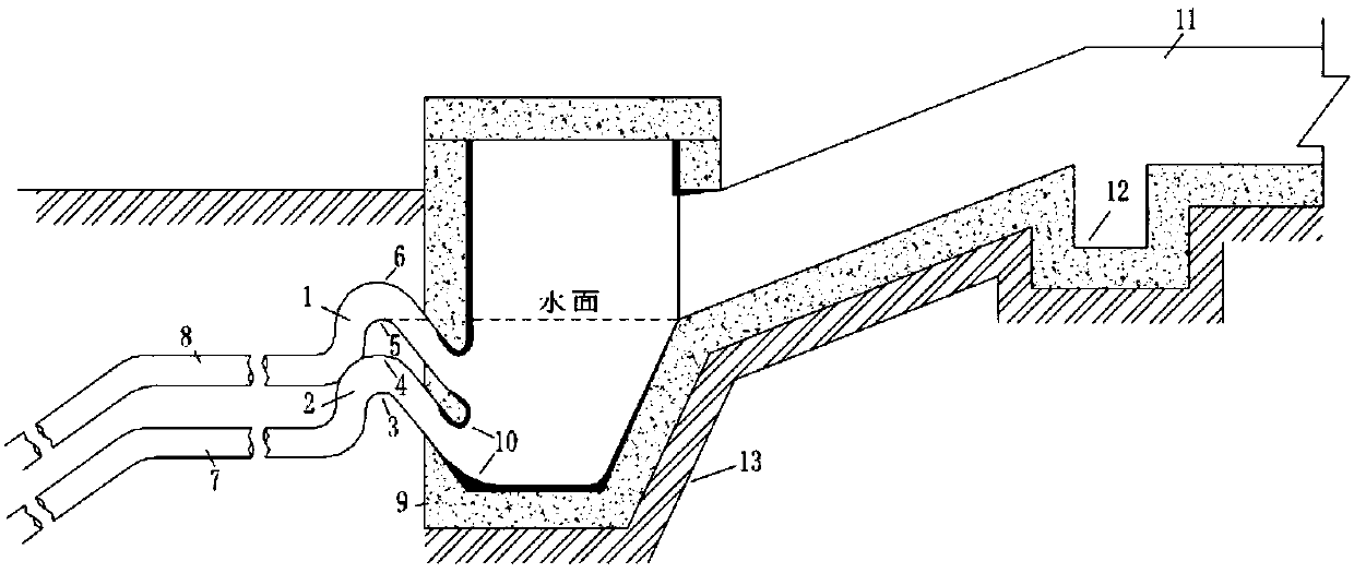
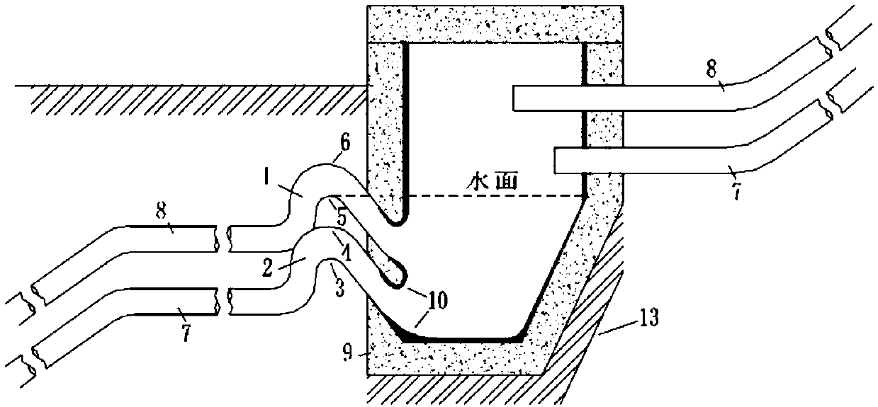
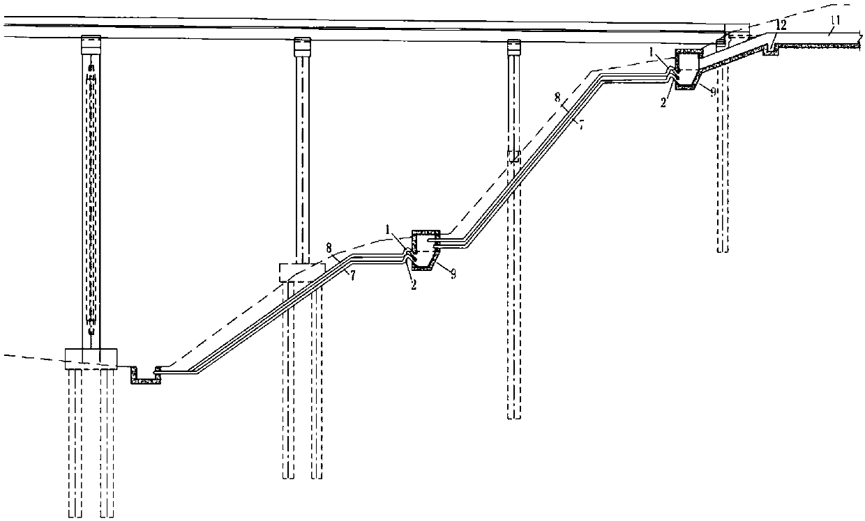
[0021] A loess gully bridge site drainage system, the drainage system includes a top bend 1, a bottom bend 2, a lower drain 7, an upper drain 8, a sump 9 and a side ditch 11; The height of the ditch is laid out; the bottom of the sump 9 is narrow and the top is wide; one end of the top bend 1 and bottom bend 2 is sealed and fixed at the bottom of the sump 9 to reserve drainage holes; the top bend 1 and bottom bend 2 The other end is horizontally connected with the upper drainage pipe 8 and the lower drainage pipe 7 respectively; the water outlets of the upper drainage pipe 8 and the lower drainage pipe 7 are located at the sump 9 at the downhill; the water inlets of the sump 9 and the side ditch 11 are cement Concrete structure; the junction of the top bend 1, bottom bend 2 and the reserved hole of the sump 9 and the inside of the sump 9 should be sealed and waterproofed; the top bend 1, bottom bend 2, upper drain 8, The lower drainage pipe 7 adopts a PVC drainage pipe with a ...

Embodiment 2

[0023] A loess gully bridge site drainage system, the drainage system includes a top bend 1, a bottom bend 2, a lower drain 7, an upper drain 8, a sump 9 and a side ditch 11; The height of the ditch is laid out; the bottom of the sump 9 is narrow and the top is wide; one end of the top bend 1 and bottom bend 2 is sealed and fixed at the bottom of the sump 9 to reserve drainage holes; the top bend 1 and bottom bend 2 The other end is horizontally connected with the upper drainage pipe 8 and the lower drainage pipe 7 respectively; the water outlets of the upper drainage pipe 8 and the lower drainage pipe 7 are located at the sump 9 at the downhill; the water inlets of the sump 9 and the side ditch 11 are cement Concrete structure; the junction of the top bend 1, bottom bend 2 and the reserved hole of the sump 9 and the inside of the sump 9 should be sealed and waterproofed; the top bend 1, bottom bend 2, upper drain 8, The lower drainage pipe 7 adopts a PVC drainage pipe with a ...


PUM


Abstract

The invention relates to a water drainage system of a loess gully bridge site. The water drainage system comprises a water-collecting groove, a bent pipe and a water drainage pipe. The water-collecting groove is arranged along the gully landform at different heights. One end of the bent pipe is fixed in a water drainage hole in the bottom of the water-collecting groove by sealing. The other end thereof is horizontally connected with a water drainage pipe. The bent pipe is arranged at the lower part of the water-collecting groove in upper and lower layers. Compared with the prior art, the waterdrainage system utilizes the height difference of the bridge site and judges the water height of the water level of the water-collecting groove and then automatically regulates the flow speed of water drainage. Therefore, a free power water pump is formed. The bridge site meets the normal water drainage need. Rainwater can be quickly discharged in harsh weather condition. The bridge site is prevented from damage by flushing. Additionally, the system is simple and quickly constructed. The maintenance and repair cost of the water drainage system in the later period is greatly reduced.

Description

technical field [0001] The invention belongs to the technical field of bridge drainage, in particular to a loess gully bridge site drainage system. technical background [0002] In the loess mountainous area, the slope is steep and deep, the ravines are vertical and horizontal, and the seasonal rainfall is concentrated. The substructure of the highway bridge crossing the loess gully is arranged along the slope and steep slope. The bottom drainage ditch is connected. During the investigation of the lower part of the bridge, it was found that 90% of the rapid flow channels and drainage ditches of the loess gully bridge had water-damaged diseases such as basement subsidence, hollowing out, sinking, and fracture to varying degrees; Most of the bridge sites use large-diameter PVC double-wall corrugated pipes for temporary drainage. The double-wall corrugated pipes still cannot meet the drainage requirements, and the drainage function is partially or completely lost. There are s...

Claims


Application Information

Patent Timeline
Patent Type & Authority Applications(China)
IPC IPC(8): E03F3/02E03F3/04
CPCE03F3/02E03F3/046
Inventor 王磊韩之江赵晓晋吴佳佳郭学兵刘志华
Owner SHANXI PROVINCIAL RES INST OF COMM
Why Eureka
Try Eureka